17-4
Catalyst 3750 Switch Software Configuration Guide
78-16180-02
Chapter 17 Configuring STP
Understanding Spanning-Tree Features
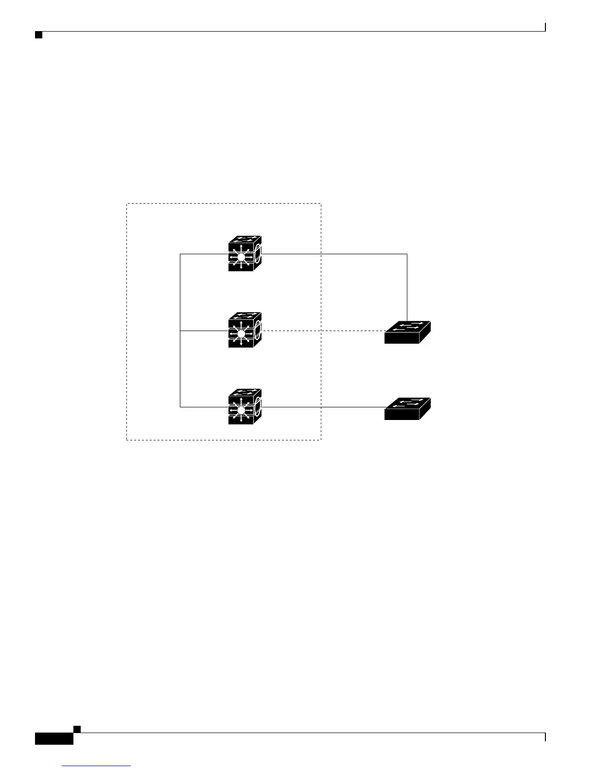
Only one outgoing port on the stack root switch is selected as the root port. The remaining switches
in the stack become its designated switches (Switch 2 and Switch 3) as shown in Figure 17-1 on
page 17-4.
• The shortest distance to the root switch is calculated for each switch based on the path cost.
• A designated switch for each LAN segment is selected. The designated switch incurs the lowest path
cost when forwarding packets from that LAN to the root switch. The port through which the
designated switch is attached to the LAN is called the designated port.
Figure 17-1 Spanning-Tree Port States in a Switch Stack
All paths that are not needed to reach the root switch from anywhere in the switched network are placed
in the spanning-tree blocking mode.
Bridge ID, Switch Priority, and Extended System ID
The IEEE 802.1D standard requires that each switch has an unique bridge identifier (bridge ID), which
controls the selection of the root switch. Because each VLAN is considered as a different logical bridge
with PVST+ and rapid PVST+, the same switch must have as many different bridge IDs as VLANs
configured on it. Each VLAN on the switch has a unique 8-byte bridge ID. The two most-significant
bytes are used for the switch priority, and the remaining six bytes are derived from the switch MAC
address.
The Catalyst 3750 switch supports the 802.1t spanning-tree extensions, and some of the bits previously
used for the switch priority are now used as the VLAN identifier. The result is that fewer MAC addresses
are reserved for the switch, and a larger range of VLAN IDs can be supported, all while maintaining the
Switch 1
Catalyst 3750 switch stack
DP Outgoing RP
Switch 2
RPStackWise
port
connections
BP
DP
Switch 3
Switch A
Switch B
RP
DP
Spanning-tree root
RPDP
RP = root port
DP = designated port
BP = blocked port
86491
 Loading...