33-2
Catalyst 3750 Switch Software Configuration Guide
78-16180-02
Chapter 33 Configuring EtherChannels
Understanding EtherChannels
EtherChannel Overview
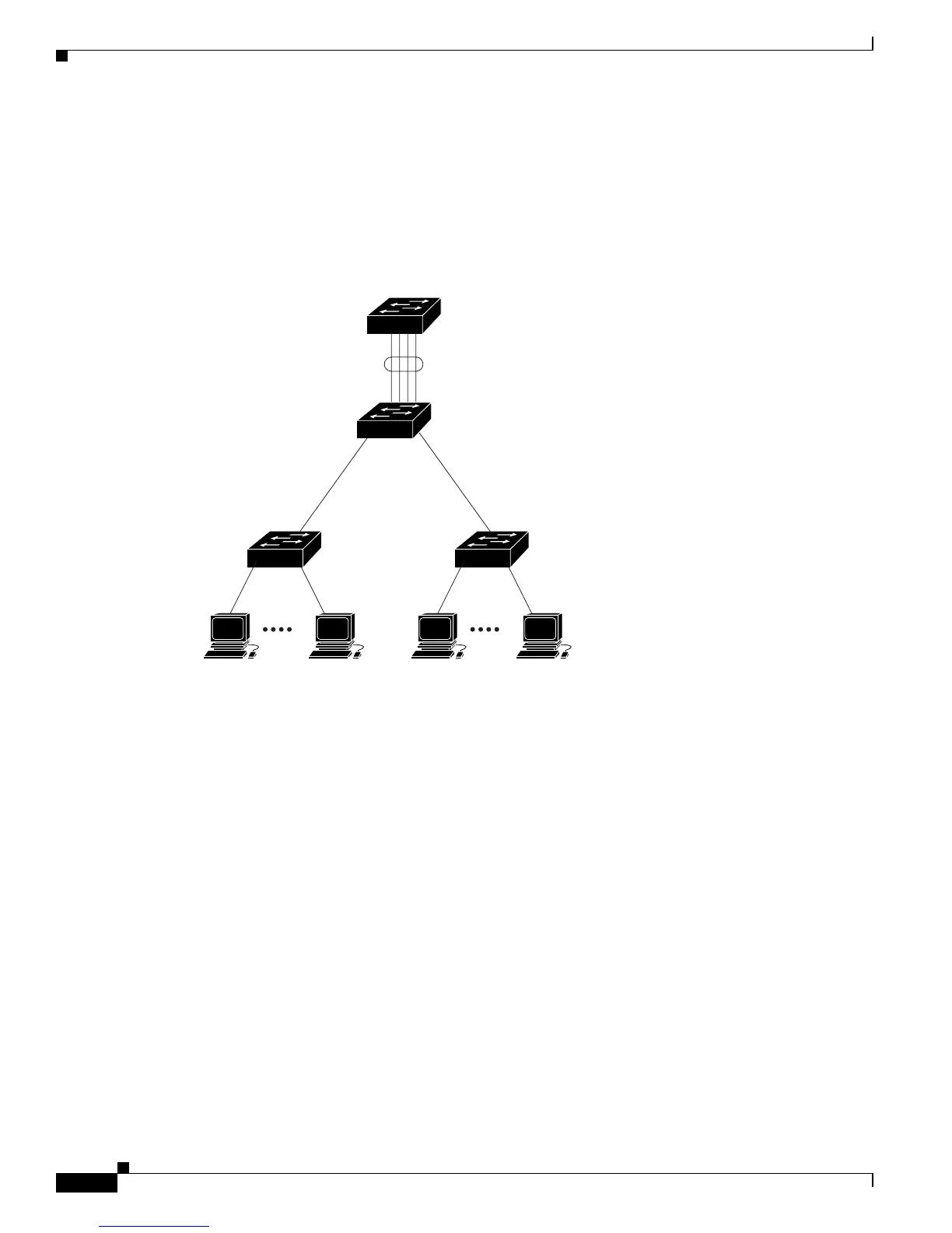
An EtherChannel consists of individual Fast Ethernet or Gigabit Ethernet links bundled into a single
logical link as shown in Figure 33-1.
Figure 33-1 Typical EtherChannel Configuration
The EtherChannel provides full-duplex bandwidth up to 800 Mbps (Fast EtherChannel) or 8 Gbps
(Gigabit EtherChannel) between your switch and another switch or host.
Each EtherChannel can consist of up to eight compatibly configured Ethernet ports. All ports in each
EtherChannel must be configured as either Layer 2 or Layer 3 ports. For Catalyst 3750 switches, the
number of EtherChannels is limited to 12. For more information, see the “EtherChannel Configuration
Guidelines” section on page 33-11. The EtherChannel Layer 3 ports are made up of routed ports. Routed
ports are physical ports configured to be in Layer 3 mode by using the no switchport interface
configuration command. For more information, see the Chapter 11, “Configuring Interface
Characteristics.”
You can create an EtherChannel on a standalone switch, on a single switch in the stack, or on multiple
switches in the stack (known as cross-stack EtherChannel). See Figure 33-2 and Figure 33-3.
If a link within an EtherChannel fails, traffic previously carried over that failed link changes to the
remaining links within the EtherChannel. A trap is sent for a failure, identifying the switch, the
EtherChannel, and the failed link. Inbound broadcast and multicast packets on one link in an
EtherChannel are blocked from returning on any other link of the EtherChannel.
101237
Catalyst 8500
series switch
Gigabit EtherChannel
Workstations
10/100
Switched
links
Workstations
10/100
Switched
links
1000BASE-X 1000BASE-X
 Loading...