InteliLite Global Guide
25
IMPORTANT: When the controller is power up only by USB and the USB is disconnected then the
actual statistics is lost.
Note: Suitable conductor protection shall be provided in accordance with NFPA 70, Article 240.
Note: Low voltage circuits (35 volts or less) shall be supplied from the engine starting battery or an isolated
secondary circuit.
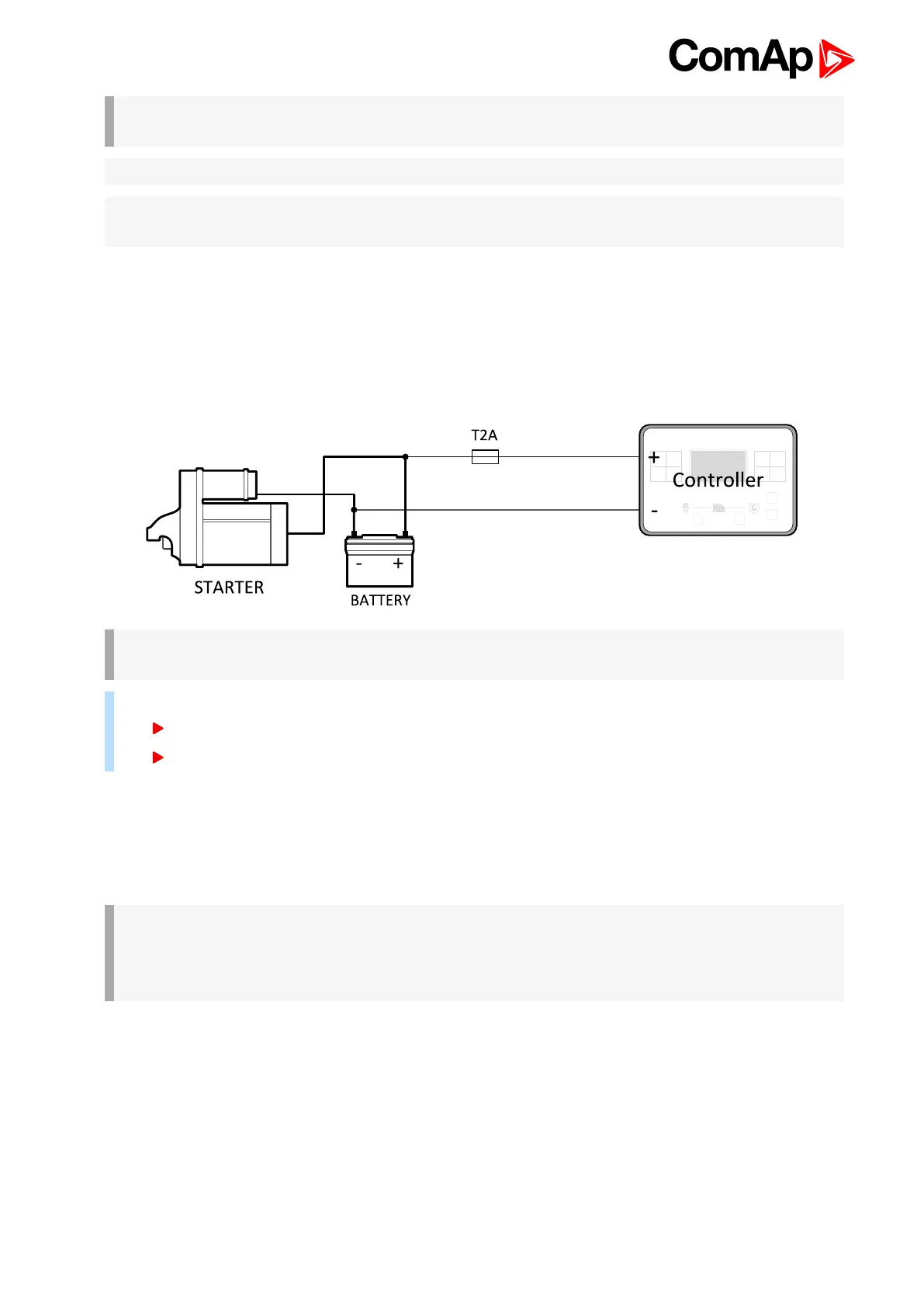
Power supply fusing
A two-amp fuse should be connected in-line with the battery positive terminal to the controller and modules.
These items should never be connected directly to the starting battery. Fuse value and type depends on number
of connected devices and wire length. Recommended fuse (not fast) type - T2A. Not fast due to internal
capacitors charging during power up.
IMPORTANT: 2 A fuse is calculated without BOUT consumption nor extension modules. Real value
of fuse depends on consumption of binary outputs and modules.
Example: Maximal consumption of binary outputs can be 22 A
2 x 10 A on high current outputs (for 10 seconds)
2 A on all others binary outputs
4.4.4 Measurement wiring
Use 1.5 mm
2
cables for voltage connection and 2.5 mm
2
for current transformers connection. Adjust Connection
type (page 157), Nominal Voltage Ph-N (page 158), Nominal Voltage Ph-Ph (page 159), Nominal Current (page
156), PT Ratio (page 159) and CT Ratio (page 157) by appropriate setpoints in the Basic Settings group.
IMPORTANT: Risk of personal injury due to electric shock when manipulating voltage terminals
under voltage. Be sure the terminals are not under voltage before touching them.
Do not open the secondary circuit of current transformers when the primary circuit is closed. Open
the primary circuit first.
Current measurement wiring
The number of CT’s is automatically selected based on selected value of setpoint Connection type (page 157)
[3Ph4Wire / High Leg D / 3Ph3Wire / Split Ph / Mono Ph].
Generator currents and power measurement is suppressed if current level is bellow <1% of CT range.
To ensure proper function:

 Loading...