InteliLite Global Guide
36
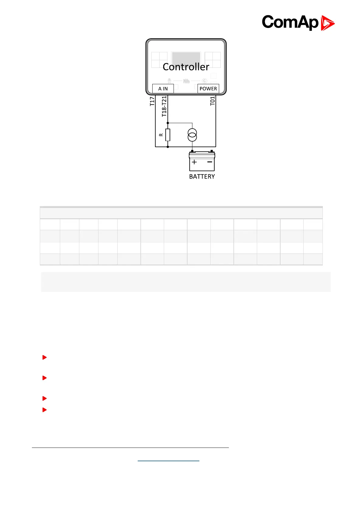
Image 4.13 Wiring of analog input with current sensor
0 - 22 mA
mA 0 1 2 3 4 5 6 7 8 9 10 11
Ω 100 133 167 202 241 283 328 375 431 489 553 625
mA 12 13 14 15 16 17 18 19 20 21 22
Ω 707 793 894 1007 1136 1287 1460 1666 1914 2222 2596
Note: This is a conversion of current from current sensor to appropriate resistance value. Use resistance
values in LiteEdit2015 to create your specific curve. These values should be used in "Ohm" column.
4.4.10 CAN bus and RS485 wiring
CAN bus wiring
The wiring of the CAN bus communication should be provided in such a way that the following rules are
observed:
The maximum length of the CAN bus depends on the communication speed. For a speed of 250 kbps, which
is used on the CAN1 bus (extension modules, ECU), the maximum length is 200 m.
The bus must be wired in linear form with termination resistors at both ends. No nodes are allowed except on
the controller terminals.
Shielded cable
1
has to be used, shielding has to be connected to the terminal T01 (BATT -).
External units can be connected on the CAN bus line in any order, but keeping line arrangement (no tails, no
star) is necessary.
1
Recommended data cables: BELDEN (http://www.belden.com) - for shorter distances: 3105A Paired - EIA
Industrial RS-485 PLTC/CM (1x2 conductors); for longer distances: 3106A Paired - EIA Industrial RS-485
PLTC/CM (1x2+1 conductors)

 Loading...