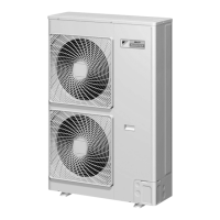
SiBE18-821_C Outdoor Unit
Printed Circuit Board Connector Wiring Diagram 27
1. Outdoor Unit
1.1 RMXS112/140/160E8V1B
Connectors and
Other Parts
[A1P]: Main PCB
[A2P]: Service PCB
[A3P]: Noise Filter PCB
[A4P]: Cool / Heat Selector PCB
1) X5A Connector to service PCB (A2P)
2) X11A Connector for outdoor temperature thermistor
3) X12A Connector for thermistors
(suction pipe 1, suction pipe 2, outdoor heat exchanger, discharge pipe)
4) X13A Connector for thermistors (subcooling outlet, liquid pipe 1, liquid pipe 2)
5) X17A Connector for high pressure sensor
6) X18A Connector for low pressure sensor
7) X21A Connector for electronic expansion valve coil (main)
8) X22A Connector for electronic expansion valve coil (subcooling)
9) X25A Connector for solenoid valve coil (four way valve)
10)X26A Connector for solenoid valve coil (hot gas bypass valve)
11)X27A Connector for solenoid valve coil (unloading)
12)X28A Connector for crankcase heater
13)X32A Connector for high pressure switch
14)X37A Connector for power supply for optional PCB (16 VDC)
15)X51A Connector for capacity setting adaptor
∗
Refer to page 137 for detail.
16)X66A Connector for cool / heat selector PCB (A4P)
17)X81A Connector for terminal board (inter-unit wiring)
18)X106A Connector for fan motor (upper)
19)X107A Connector for fan motor (lower)
20)X111A Connector for fin thermistor
21)LD, LE Connector for reactor
22)LC, NC Terminal for noise filter PCB (A3P)
23)P Connector for capacitor C4 +
24)N Connector for capacitor C4 –
25)U, V, W Connector for compressor
26)F4U Fuse (6.3 A / 250 V)
27)F6U Fuse (5.0 A / 250 V)
28)HAP Operation pilot lamp (LED for service monitor: green)
1) X205A Connector for main PCB (A1P)
2) H1P - H8P LED for service monitor (orange)
3) BS1 - BS5 Push button switch (mode, set, return, test, reset)
4) DS1 DIP switch
1) LA, NA Terminal for terminal board (power supply)
2) LB, NB Terminal for main PCB (A1P)
3) E Terminal for earth
4) F1U Fuse (6.3 A / 250 V)
1) X1A Connector for main PCB (A1P)
2) X1M Terminal for cool / heat selector

 Loading...


