5. Fill the installation with water.
6. Vent the installation.
7. Top up with more water if necessary.
8. Check the tightness of the gas and water connections.
9. Put the boiler back into operation.
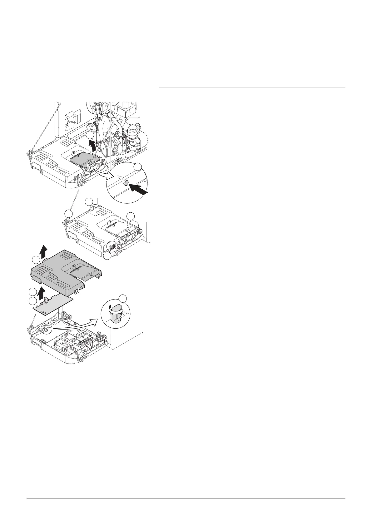
10.3.8 Replacing the control PCB
If a faulty control PCB in the instrument box needs to be replaced, proceed
as follows:
1. Open the instrument box by pressing in the clip fastener at the side.
2. Open the jumpers at the side of the instrument box in the correct
order. The order is indicated by the numbers of the instrument box.
3. Remove the top of the instrument box.
4. Turn the key on the CU-GH08 PCB.
5. Remove all cables from the CU-GH08 PCB.
6. Replace the CU-GH08 PCB
7. Reassemble in the reverse order.
Fig.102 Access to the connectors
AD-0001351-03
1
2.1
2.2
2.3
2.4
4
5
6
3
1
10 Maintenance
7686707 - v.01 - 06092018 AMC 109
 Loading...