Type Principle Description
Permitted manufacturers
(1)
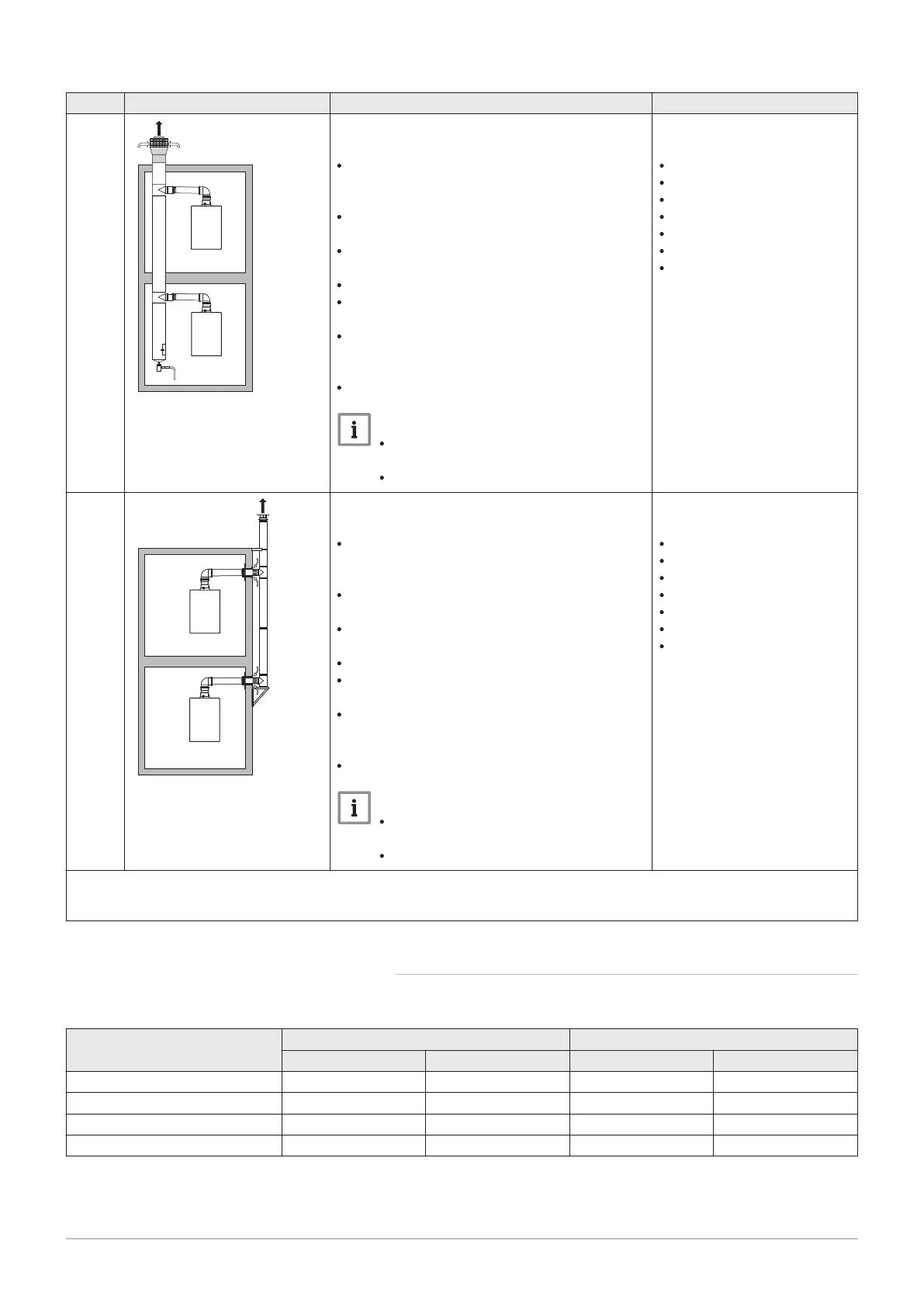
C
(10)3(X)
Combined air supply and flue gas outlet system
(CLV) with overpressure
Minimum permitted pressure difference between
the air supply and the flue gas outlet is -200 Pa
(including -100 Pa wind pressure).
The channel must be designed for a nominal
flue gas temperature of 25°C
Place a condensation drain, equipped with a si
phon, at the bottom of the channel.
Maximum permissible recirculation of 10%.
The common outlet should be appropriate for a
pressure of at least 200 Pa.
The roof feed-through must be designed for this
configuration and must cause a draught in the
channel.
A draught diverter is not permitted.
Important
The fan speed must be adapted for
this configuration.
Contact us for more information.
Connecting material to the
common channel:
Centrotherm
Cox Geelen
Muelink & Grol
Natalini
Poujoulat
Skoberne
Ubbink
C
(12)3(X)
Common flue gas outlet and individual air supply
(half CLV)
Minimum permitted pressure difference between
the air supply and the flue gas outlet is -200 Pa
(including -100 Pa wind pressure).
The channel must be designed for a nominal
flue gas temperature of 25°C
Place a condensation drain, equipped with a si
phon, at the bottom of the channel.
Maximum permissible recirculation of 10%.
The common outlet should be appropriate for a
pressure of at least 200 Pa.
The roof feed-through must be designed for this
configuration and must cause a draught in the
channel.
A draught diverter is not permitted.
Important
The fan speed must be adapted for
this configuration.
Contact us for more information.
Connecting material to the
common channel:
Centrotherm
Cox Geelen
Muelink & Grol
Natalini
Poujoulat
Skoberne
Ubbink
(1) The material must also satisfy the material property requirements from the relevant chapter.
(2) EN 15502-2-1: 0.5 mbar suction due to depression
(3) See table for shaft or duct requirements
6.5.2
Requirements for shaft for C
93
Tab.14 Minimum dimensions of shaft or duct
Version (D) Without air supply With air supply
Ø duct □ duct Ø duct □ duct
Rigid 60 mm 110 mm 110 x 110 mm 120 mm 110 x 110 mm
Rigid 80 mm 130 mm 130 x 130 mm 140 mm 130 x 130 mm
Concentric 60/100 mm 120 mm 120 x 120 mm 120 mm 120 x 120 mm
Concentric 80/125 mm 145 mm 145 x 145 mm 145 mm 145 x 145 mm
6 Installation
7686707 - v.01 - 06092018 AMC 31
 Loading...