24 INSTALLATION AND OPERATION MANUAL 25-16327-B November 2020 www.eaton.com
Section 1: System installation and design
Input/outputs
Panel outputs
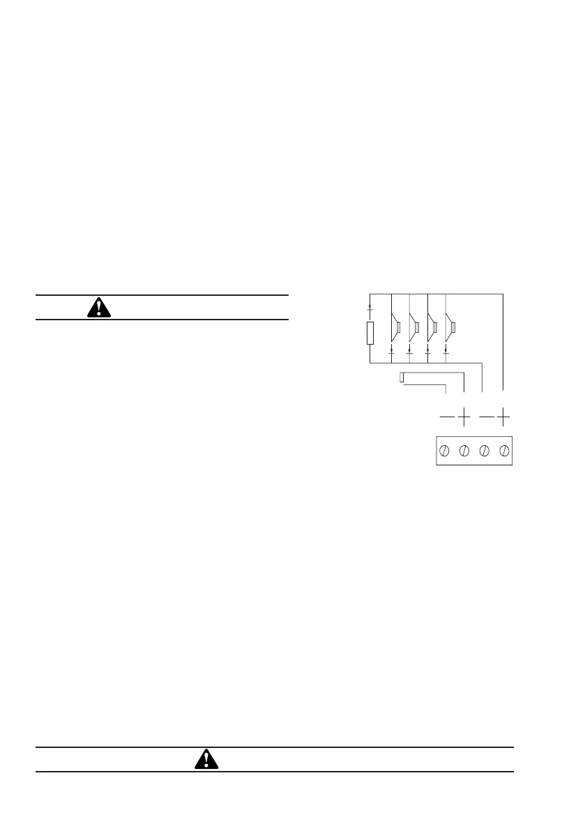
Panel Sounders: (OPTION 7.8 EN54 PT 2)
Two pairs of outputs are provided. ONLY polarised equipment should be used.
Ensure the polarity of the connections are observed at all times and end of line
resistors & Diodes) are fitted for correct operation.
The total alarm load across all sounder outputs = 1.5 Amp
All outputs are fused with 1.6 Amp Glass fuse Alarm devices should be spread
equally across the 2 soundercircuits.
WARNING
Do not exceed the rated output current.
All sounders must be polarised
OUTPUT TO FAULT WARNING ROUTING
EQUIPMENT (OPTION 9.4.1C EN54 PT 2)
This output, which is fused and monitored
using 2k end ofline resistor is used for the
transmission of fault signals to fault warning
routing equipment. This output is monitored
using 2k0 end of line resistor and it current
limited to 30mA.
Under normal conditions it operates by providing 12vdc which can be connected
directly to a 24v auxiliary device
(relay).It is current limited to 30 mA.
Under fault conditions or even if the Panel is switched off, this output will switch to 0
volts. Ensure the polarity of the connections is observed at all times and end of line
resistors (2k0 5%) are fitted for correct operation.
Auxiliary Relay (OPTION NOT REQUIRED BY EN54)
This output is a volt free contact, which is protected by a polyswitch. It is rated at
24 Volts 1Amp. If operated under a fire alarm condition , this output will remain
energised until the fire alarm is reset.
AUXILIARY DC OUTPUT (OPTION NOT DEFINED BYEN54)
A 24 Vdc output is provided. This output is protected by a polyswitch. This output can
be used to power fire or fault auxiliary equipment. Please ensure that all equipments
connected to this output will only draw current when a fire condition exists.
WARNING
Do not exceed the rated output current.
End of line device.
Both sounder circuits must
be terminated with an end
of line device.
 Loading...