98 INSTALLATION AND OPERATION MANUAL 25-16327-B November 2020 www.eaton.com
Section 4: Appendix
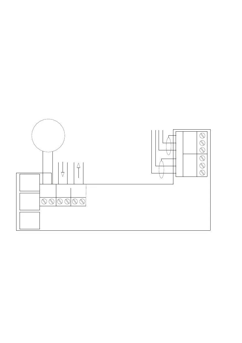
4-20mA interface wiring (CGI420, CIT420, CGI420R, CIT420R)
Installation
1. Separate the two halves of the unit
2. Drill out (or knock out) the required cable entries in the surface mounting back-box
3. Fit the back-box in position and pass the wires into it
4. Connect the unit according to the diagram below
5. Set the required threshold levels via the DIL switches
Standard connections
ote: N
Recommended Loop Cable Type: FIRETUF, FP200, MICC No addressing of the
interface is required. See control panel operation for details. There are no serviceable
parts so no maintenance procedures apply. 24V DC must always be present.
4-20mA
Gas detector
Addressable
loop
Loop comms
Out
E - +
In
E - +
24V
Input
4-20mA
Input
- +
PSU
Input
0V 24V
PSU
Output
0V 24V
JP1
DIL
Switches
JP2
DIL
Switches
JP3
DIL
Switches
24V
Output
 Loading...