46
10.16 Inverter (Motor Control Unit)
10.16.1 General characteristics
The Inverter (Motor Control Unit) use a new asynchronous motor,
with 2 poles, three-phase, with high performance and low noise
levels.
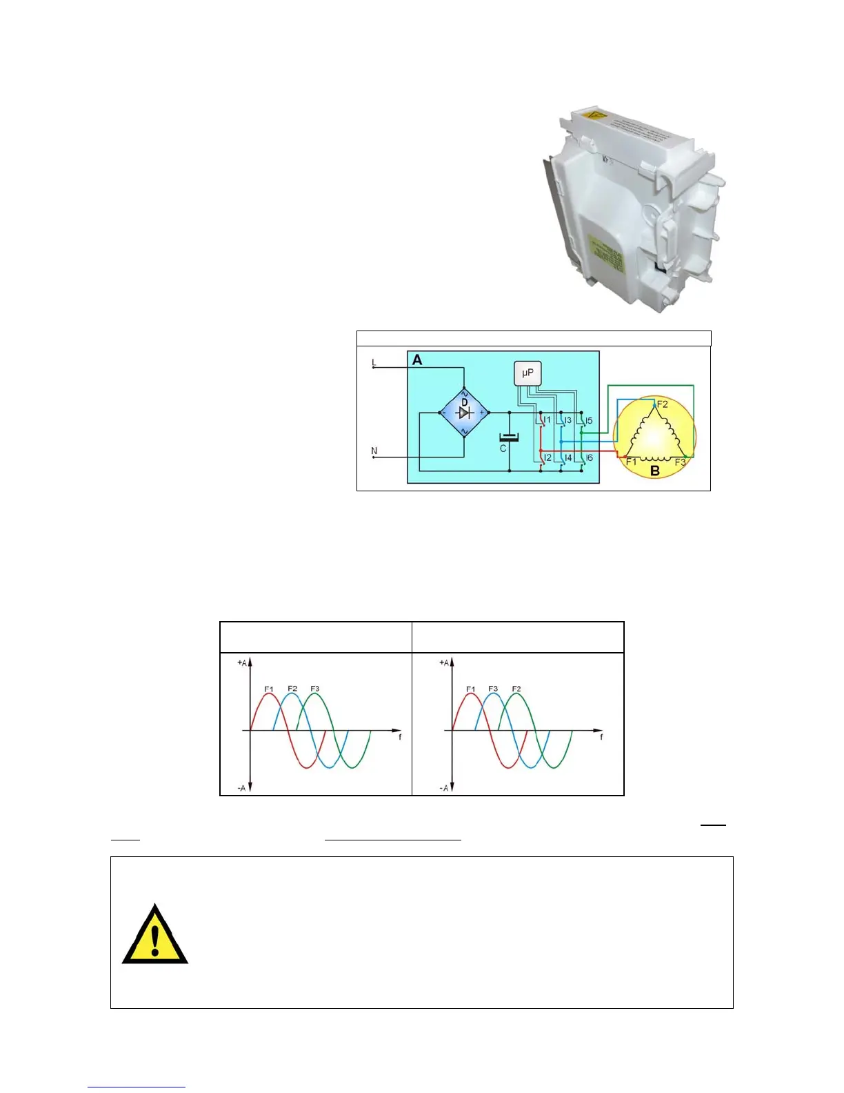
L = Phase
N = Neutral
A = “INVERTER” board
B = Motor
C = Capacitor
D = Diodes
I1÷6 = Power transistors
F1÷3 = Motor connectors
µP = Micro Processor
To transform the single-phase electricity (available in our homes) into three-phase electricity, a new circuit
board is used (A) to transform the energy from single-phase to three-phase, which can be modulated in
breadth and frequency respectively to adjust the power and number of revolutions of the motor.
Single-phase electricity (applied to connectors L-N), is rectified by the diode jumper (D), so there is a direct
voltage of 310V at the ends of capacitor C, which through the combination of the opening and closing of
switches I1÷I6 (piloted by the µprocessor) determines the piloting voltage and frequency of the motor.
Clockwise rotation of the
motor
Anti-clockwise rotation of the
motor
During the spin phases, the microprocessor can perform, depending on the software configuration, the anti-
foam check, where featured, and the anti-unbalancing check.
Any work on electrical appliances must only be carried out by qualified
technicians.
Unplug the appliance before accessing internal components.
When replacing the “INVERTER” board, do not open the plastic casing,
because some parts are subject to high voltage values and some condensers
remain loaded for a long time at dangerous voltage levels even after being
unplugged.
Accidental physical contact may cause electric shocks.
“INVERTER” operating diagram
 Loading...