5
Reference Manual
00809-0100-4804, Rev CB
Installation
November 2016
Installation
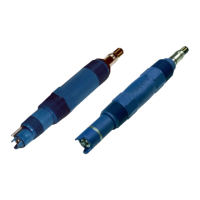
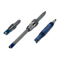
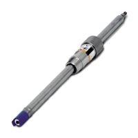
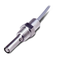
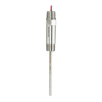
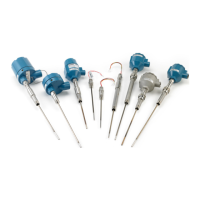
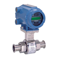
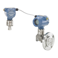
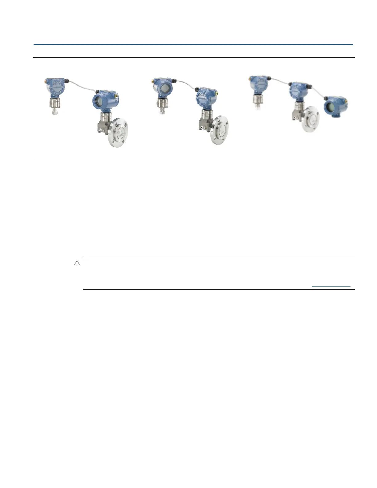
Figure 2-1. Rosemount ERS Models and Possible Configurations
2.4 Considerations
2.4.1 General
Measurement performance depends upon proper installation of each transmitter and impulse piping.
Mount each Rosemount 3051S ERS Transmitter close to the process and use minimum piping to achieve
best performance. Also, consider the need for easy access, personnel safety, practical field calibration,
and a suitable environment. Install each sensor to minimize vibration, shock, and temperature
fluctuation.
Note
Install the enclosed pipe plugs (found in the box) in any unused conduit openings. For proper straight
and tapered thread engagement requirements, see the appropriate approval drawings in Appendix B:
Product Certifications. For material compatibility considerations, see Material Selection Technical Note.
2.4.2 Mechanical
For dimensional drawing information, refer to “Dimensional drawings” on page 73.
For steam service or for applications with process temperatures greater than the limits of each
Rosemount 3051S ERS Transmitter, do not blow down impulse piping through either sensor. Flush lines
with the blocking valves and refill lines with water before resuming measurement.
If a Rosemount 3051S ERS Transmitter is mounted on its side, position the flange/manifold to ensure
proper venting or draining.
Field terminal side of housing
Mount each Rosemount ERS Sensor so the terminal side is accessible. Clearance of 0.75-in. (19 mm) is
required for cover removal.
Electronics side of housing
Provide 0.75-in. (19 mm) of clearance for units without an LCD display. Three inches of clearance is
required for cover removal if an LCD display is installed.
Rosemount
3051SAM In-Line
(Secondary)
Rosemount 3051SAL Coplanar
with FF Seal (Primary)
Rosemount 3051SAM
In-Line (Primary)
Rosemount 3051SAL Coplanar
™
with FF Seal (Secondary)
Rosemount
3051SAM In-Line
(Secondary)
Rosemount 3051SAL Coplanar with
FF Seal and Remote Display
(Primary)
 Loading...