15
Reference Manual
00809-0100-4804, Rev CB
Installation
November 2016
Installation
2.5.6 Connect wiring and power up
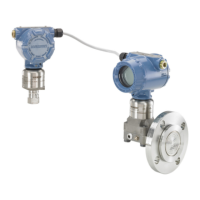
Typical Rosemount ERS System
1. Remove the housing cover labeled “Field Terminals” on both Rosemount 3051S ERS Transmitter.
2. Using the Rosemount ERS Madison Cable (if ordered) or an equivalent 4-wire shielded assembly per
the specifications detailed on page 16, connect the 1, 2, A, and B terminals between the two sensors
per Figure 2-10. Maintain uniform twist in wires as close as possible to the screw terminals.
3. Connect the Rosemount ERS System to the control loop by wiring the “+” and “–” PWR/COMM
terminals of the Rosemount 3051S ERS Primary Transmitter to the positive and negative leads,
respectively.
4. Plug and seal all unused conduit connections.
5. If applicable, install wiring with a drip loop. Arrange the drip loops so the bottom is lower than the
conduit connections and the transmitter housings.
6. Reinstall and tighten the housing covers on both sensors so metal contacts metal to meet
explosion-proof requirements.
Rosemount 3051S ERS System with optional remote display and
interface
1. Remove the housing cover labeled “Field Terminals” on both Rosemount ERS Sensors and the remote
housing.
2. Using the Rosemount ERS Madison Cable (if ordered) or an equivalent 4-wire shielded assembly per
the specifications detailed on page 16, connect the 1, 2, A, and B terminals between the two sensors
and remote housing in a “tree” (Figure 2-11) or daisy-chain (Figure 2-12) configuration. Maintain
uniform twist in wires as close as possible to the screw terminals.
3. Connect the Rosemount ERS System to the control loop by wiring the “+” and “–” PWR/COMM
terminals of the remote housing to the positive and negative leads, respectively.
4. Plug and seal all unused conduit connections.
5. If applicable, install wiring with a drip loop. Arrange the drip loops so the bottom is lower than the
conduit connections and the transmitter housings.
6. Reinstall and tighten all housing covers so metal contacts metal to meet explosion-proof
requirements.
Note
I.S. barriers with inductive loads greater than 1 mH should not be used with the Rosemount ERS System
and may cause the device to not function properly.
 Loading...
