29
Reference Manual
00809-0100-4804, Rev CB
Configuration
November 2016
Configuration
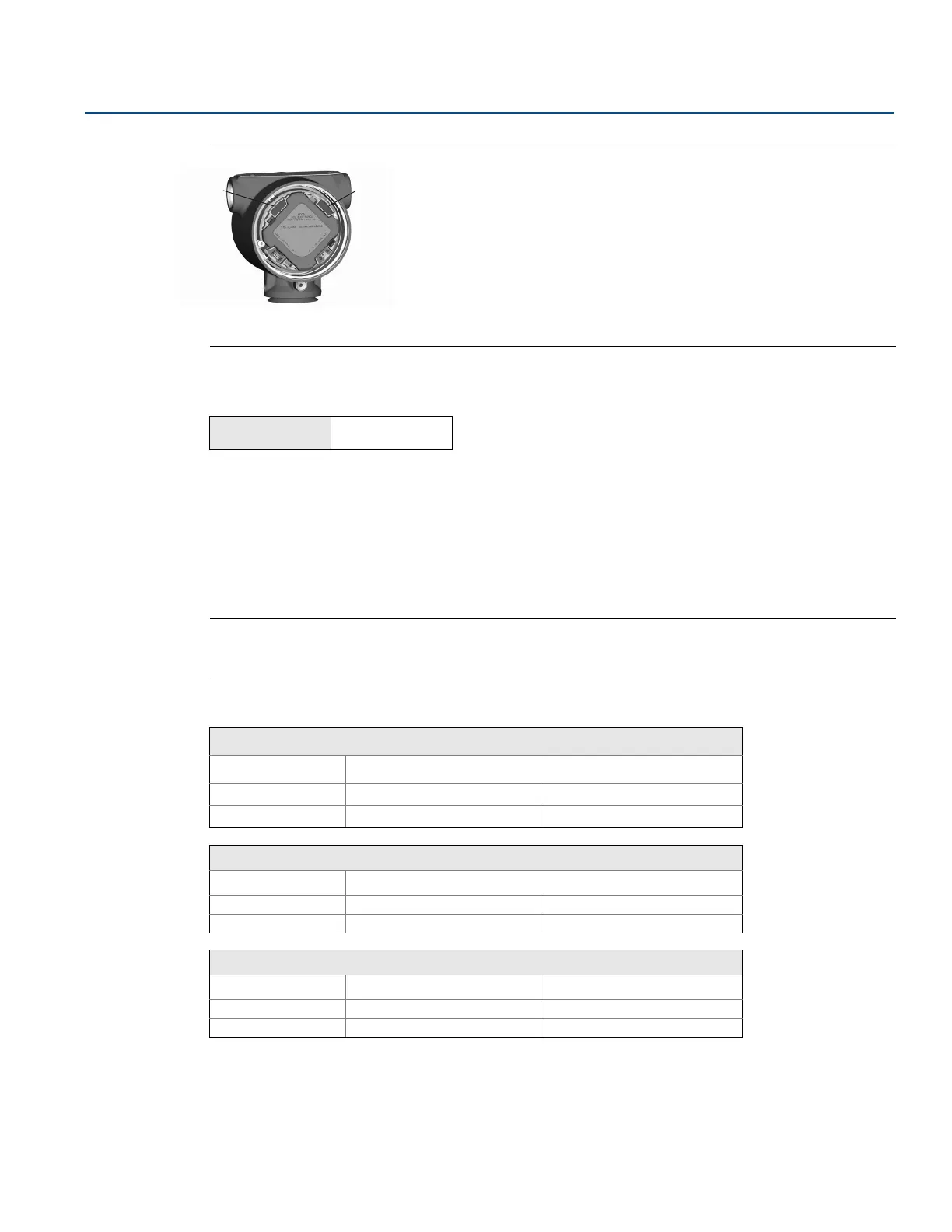
Figure 3-1. Zero and Span Buttons
A. Zero
B. Span
3.4.6 Alarm and saturation levels
The Rosemount 3051S ERS Transmitter automatically and continuously performs self-diagnostic
routines. If a self-diagnostic routine detects a failure, the ERS System will drive the output to the
configured alarm value that is based on the position of the failure mode alarm switch (see “Configure
process alerts” on page 38). The ERS System will also drive the output to configured saturation values if
the applied pressure goes outside the 4–20 mA range values.
The Rosemount 3051S ERS System has three options for configuring the failure mode alarm and
saturation levels:
Note
The ERS System will drive the output to alarm level (high or low) if the pressure applied to either sensor is
outside of the Lower sensor limit (LSL) or Upper sensor limit (USL).
Table 3-2. Alarm and Saturation Values
Additional considerations when using custom alarm and saturation values:
Low alarm must be less than low saturation
High alarm must be higher than high saturation
Alarm and saturation levels must be separated by at least 0.1 mA.
Fast Keys
2, 1, 1, 5
Rosemount (standard)
Switch position Saturation level Alarm level
Low 3.9 mA 3.75 mA
High 20.8 mA 21.75 mA
NAMUR-compliant
Switch position Saturation level Alarm level
Low 3.8 mA 3.6 mA
High 20.5 mA 22.5 mA
Custom
Switch position Saturation level Alarm level
Low 3.7 — 3.9 mA 3.54 — 3.8 mA
High 20.1 — 21.5 mA 20.2 — 23.0 mA
 Loading...