50
Reference Manual
00809-0100-4804, Rev CB
Operation and Maintenance
November 2016
Operation and Maintenance
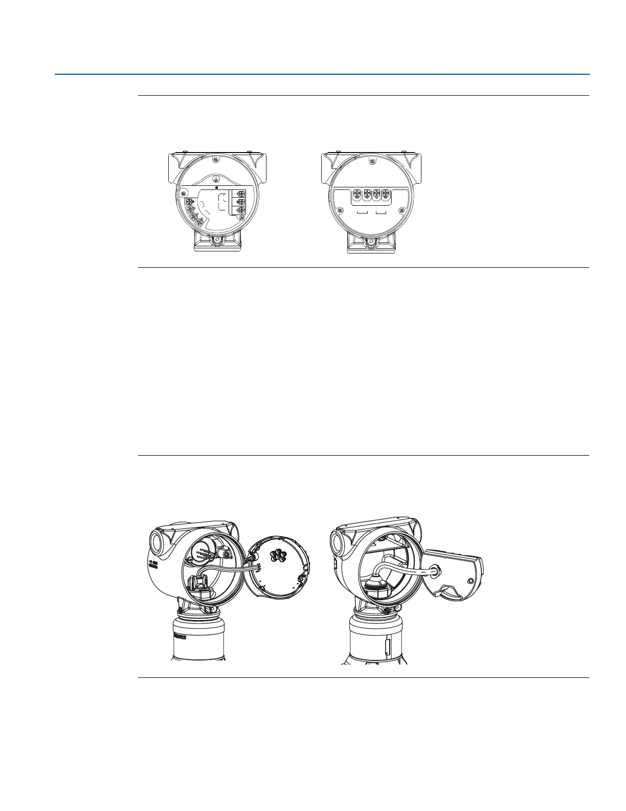
Figure 4-2. Terminal Blocks
4.5.4 Removing the electronics
To remove the electronics feature board from a Rosemount 3051S ERS Primary Transmitter:
1. Remove the housing cover opposite the field terminal side.
2. Remove the LCD display (if applicable). Do this by holding in the two clips and pulling outward. This
will provide better access to the two screws located on the electronics feature board.
3. Loosen the two small screws located on the assembly in the 8 o’clock and 2 o’clock positions.
4. Pull out the assembly to expose the SuperModule connector (see Figure 4-3).
5. Grasp the SuperModule connector and pull upwards (avoid pulling wires). Housing rotation may be
required to access locking tabs.
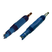
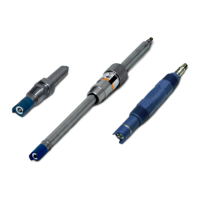
Figure 4-3. SuperModule Electrical Connector
Rosemount 3051S ERS Primary Rosemount 3051S ERS Secondary
Rosemount 3051S ERS Primary Rosemount 3051S ERS Secondary
TEST
PWR/
COMM
+
_
_
1
2
A
B
WIRE TO
ERS
SECONDARY
 Loading...