19
Reference Manual
00809-0100-4804, Rev CB
Installation
November 2016
Installation
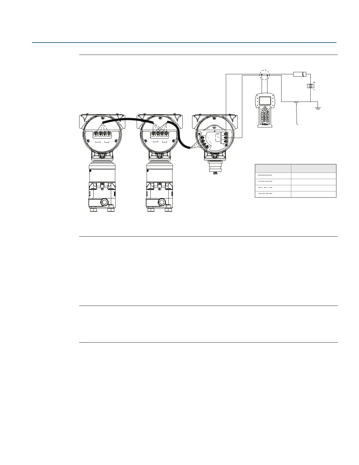
Figure 2-12. Wiring for Rosemount 3051S ERS System with Remote Display in “Daisy-Chain”
Configuration
A. Field Communicator
B. Power supply
C. 250
resistor needed for HART communications
2.5.7 Grounding
Loop wiring grounding
Do not run signal wiring in conduit or open trays with power wiring or near heavy electrical equipment.
Ground the shield of the signal wiring at any one point on the signal loop. See Figure 2-13. The negative
terminal of the power supply is a recommended grounding point.
Note
Grounding the transmitter case using the threaded conduit connection may not provide a sufficient
ground. The transient protection terminal block (option code T1) will not provide transient protection
unless the transmitter case is properly grounded. Do not run transient protection ground wire with
signal wiring; the ground wire may carry excessive current if a lightning strike occurs.
TEST
PWR/
COMM
+
_
_
1
2A B
1
2
A
B
WIRE TO ERS PRIMARY
1
2
A
B
WIRE TO
ERS
SECONDARY
WIRE TO ERS PRIMARY
A
C
B
Wiring Legend
Wire
Terminal connection
Red 1
Black 2
White A
Blue B

 Loading...