44
Reference Manual
00809-0100-4804, Rev CB
Operation and Maintenance
November 2016
Operation and Maintenance
4.3 Calibration
4.3.1 Calibration overview
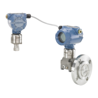
Calibrating a Rosemount ERS System involves the following tasks:
1. Configure process variables.
See “Basic setup” on page 26 for additional details on configuring the following:
Units of measure
Damping
Variable mapping
4 and 20 mA range points
Alarm and saturation levels
2. Calibrate the P
HI
and P
LO
pressure sensors.
Calibrate each pressure sensor by performing a zero/lower and an upper sensor trim.
3. Differential Pressure zero trim.
Perform a zero-trim on the Differential Pressure (DP) reading to establish a zero-based measurement.
4. Calibrate the 4–20 mA output.
Adjust the analog output to match the control loop.
Electrical shock could cause death or serious injury.
If the ERS System is installed in a high-voltage environment and a fault or installation error occurs,
high voltage may be present on the transmitter leads and terminals.
Use extreme caution when making contact with the leads and terminals.
Process leaks could result in death or serious injury.
Install and tighten all four flange bolts before applying pressure.
Do not attempt to loosen or remove flange bolts while the transmitter is in service.
Replacement equipment or spare parts not approved by Emerson
™
for use as spare parts could
reduce the pressure retaining capabilities of the transmitter and may render the instrument
dangerous.
Use only bolts supplied or sold by Emerson as spare parts.
Improper assembly of manifolds to traditional flange can damage the device.
For the safe assembly of the manifold to the transmitter flange, bolts must break the back plane of
the flange web (i.e. bolt hole) but must not contact the sensor module.
Static electricity can damage sensitive components.
Observe safe handling precautions for static-sensitive components.
 Loading...
