61
Reference Manual
00809-0100-4804, Rev CB
Safety Instrumented Systems
November 2016
Safety Instrumented Systems
Section 6 Safety Instrumented Systems
Requirements
Safety Instrumented Systems (SIS) Certification . . . . . . . . . . . . . . . . . . . . . . . . . . . . . . . . . . . . . . page 61
6.1 Safety Instrumented Systems (SIS) Certification
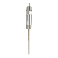
The Rosemount™ 3051S Electronic Remote Sensor (ERS)™ System is a two wire, 4–20 mA architecture
that calculates differential pressure electronically using two pressure sensors that are linked together
with a digital cable. The transmitter system uses standard, well-proven sensor boards in combination
with a microprocessor board that performs diagnostics. It is programmed to send its output to a
specified failure state, either high or low, when an internal failure is detected. It is assumed that the
4–20 mA output is used as a primary safety variable. No other output variants are covered by this report;
Type B.
SIL 2 for random integrity @ HFT = 0
SIL 3 for random integrity @ HFT = 1
SIL 3 for systematic integrity
6.1.1 Rosemount ERS Systems safety certified identification
All Rosemount 3051S Transmitters must be identified as safety certified before installing into SIS
systems.
To identify a safety certified Rosemount ERS System, verify the following information:
Model string should contain 3051SAM, 3051SAL_P, or 3051SAL_S
Software revision should be 57 or higher
Model string should contain option code QT
Maximum ERS cable length for SIS certification is 200 feet (60.96 m). Cable must also meet the
specifications from “Rosemount 3051S ERS System cable specifications” on page 16.
6.1.2 Installation in SIS applications
Installations are to be performed by qualified personnel. No special installation is required in addition to
the standard installation practices outlined in “Connect wiring and power up” on page 15. Always ensure
a proper seal by installing the electronics housing cover(s) so that metal contacts metal.
Environmental and operational limits are available in Appendix A: Specifications and Reference Data.
The loop should be designed so the terminal voltage does not drop below 16 Vdc when the transmitter
output is set to 23 mA. Refer to A.2.4: HART specifications to verify limitation.
Position the security switch to the ( ) position to prevent accidental or deliberate change of
configuration data during normal operation.
 Loading...