22
Reference Manual
00809-0100-4804, Rev CB
Installation
November 2016
Installation
Transmitter case
Always ground the transmitter case in accordance with national and local electrical codes. The most
effective transmitter case grounding method is a direct connection to earth ground with minimal
impedance (< 1 ohm). Methods for grounding the transmitter case include:
Internal ground connection: The internal ground connection screw is inside the terminal side of the
electronics housing. The screw is identified by a ground symbol
( ), and is standard on all Rosemount 3051S ERS Transmitters.
External ground connection: The external ground connection is on the outside of the SuperModule
™
housing. The connection is identified by a ground symbol ( ).
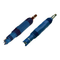
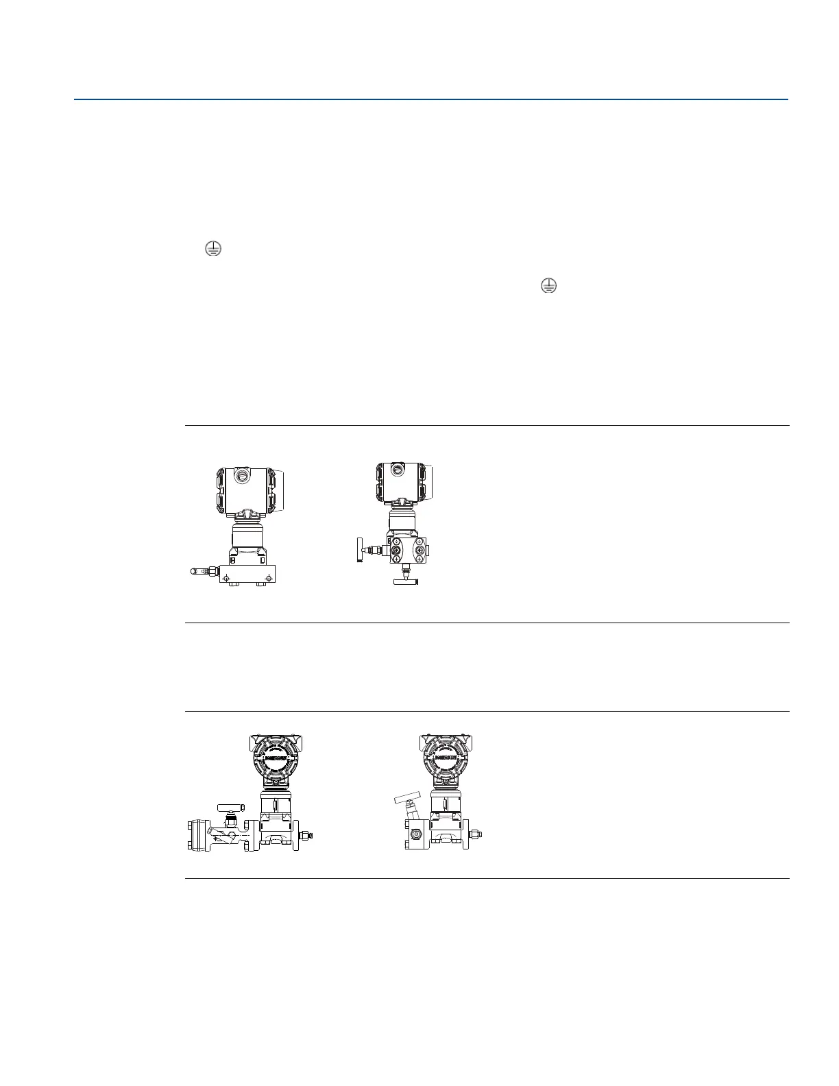
2.6 Rosemount manifolds
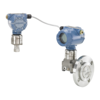
The Rosemount 305 Integral Manifold assembles directly to an Rosemount 3051S ERS Transmitter,
eliminating the need for the flange. The Rosemount 305 is available in two designs: coplanar (bottom
process connections) and traditional (side process connections).
Figure 2-15. Rosemount 305 Integral Manifolds
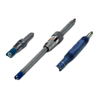
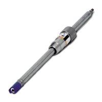
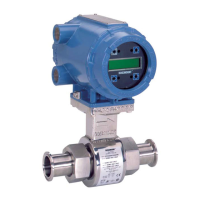
The Rosemount 304 Conventional Manifold assembles directly to an instrument flange for easy servicing
and retrofitting. The Rosemount 304 is available in two basic styles: traditional (flange 3 flange and
flange 3 pipe) and wafer.
Figure 2-16. Rosemount 304 Conventional Manifolds
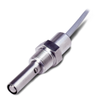
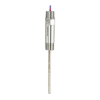
The Rosemount 306 Manifold assembles directly to an in-line style transmitter and is available with male
or female
1
/2-in. NPT process connections.
 Loading...