24
Reference Manual
00809-0100-4804, Rev CB
Installation
November 2016
Installation
2.6.3 Rosemount 306 Manifold installation procedure
To install a Rosemount 306 In-Line Manifold to a Rosemount 3051S ERS Transmitter:
1. Place the Rosemount 3051S ERS Transmitter into a holding fixture.
2. Apply appropriate thread paste or tape to the threaded instrument end of the manifold.
3. Count the total threads on the manifold before starting assembly.
4. Start turning the manifold by hand into the process connection on the transmitter. Be sure the thread
tape does not strip.
5. Wrench-tighten the manifold into the process connection. The minimum torque value is 425 in-lbs.
6. Count how many threads are still showing. The minimum thread engagement is three revolutions.
7. Subtract the number of threads showing (after tightening) from the total threads to calculate the
revolutions engaged. Further tighten until a minimum of three rotations is achieved.
8. For block and bleed manifold, verify the bleed screw is installed and tightened. For two-valve
manifold, verify the vent plug is installed and tightened.
9. Leak-check assembly to maximum pressure range of transmitter.
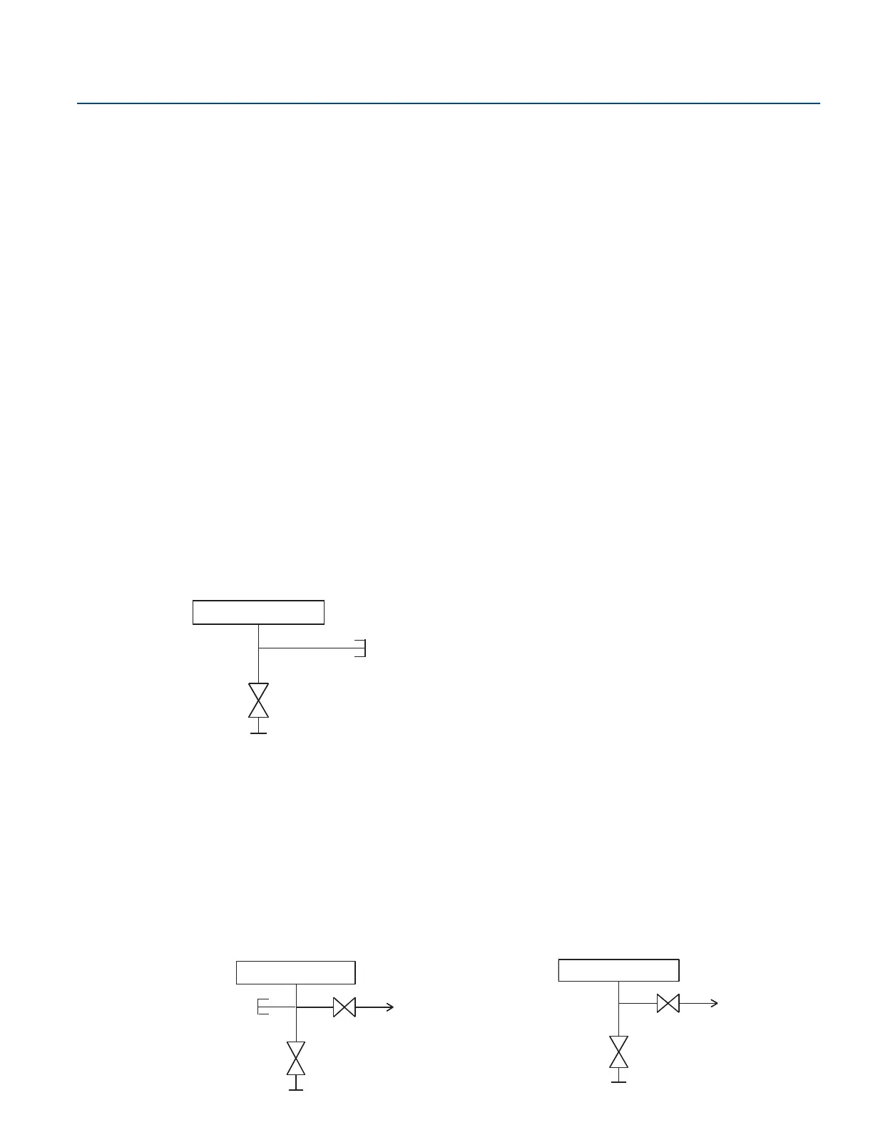
2.6.4 Manifold valve configurations
Block-and-bleed manifold
The block-and-bleed configuration is available on the Rosemount 306 Manifold for use with in-line gage
and absolute pressure transmitters. A single block valve provides instrument isolation, and a plug
provides draining/vent capabilities.
A. Transmitter
B. Bleed screw
C. Process
D. Isolate
Two-valve manifold
The two-valve configuration is available on the Rosemount 304, 305, and 306 Manifolds for use with
gage and absolute pressure transmitters. A block valve provides instrument isolation, and a drain/vent
valve allows for venting, draining, or calibration.
Rosemount 304 2-Valve Configuration Rosemount 305 and 305 Valve Configuration
 Loading...