62
Reference Manual
00809-0100-4804, Rev CB
Safety Instrumented Systems
November 2016
Safety Instrumented Systems
6.1.3 Configuring in SIS applications
Use any HART
®
-capable configuration tool to communicate with and verify configuration of the
Rosemount ERS System.
Note
Transmitter output is not safety-rated during the following; configuration changes, multidrop, and loop
test. Alternative means should be used to ensure process safety during transmitter configuration and
maintenance activities.
Damping
User-selected damping will affect the transmitters ability to respond to changes in the applied process.
The damping value + response time must not exceed the loop requirements.
Reference “Damping” on page 27 to change damping value.
Alarm and saturation levels
Distributed Control System (DCS) or safety logic solver should be configured to match transmitter
configuration.
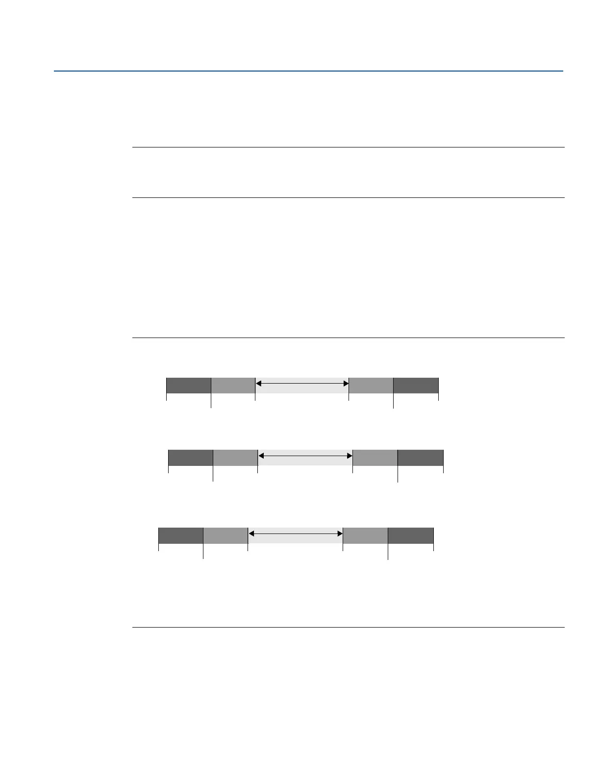
Figure 6-1
identifies the three alarm levels available and their operation values.
Figure 6-1. Alarm Levels
Rosemount alarm level
Namur alarm level
Custom alarm level
1. Transmitter Failure, hardware or software alarm in LO position.
2. Transmitter Failure, hardware or software alarm in HI position.
Normal operation
4 mA
20 mA
20.8 mA
high saturation
21.75
(2)
3.9 mA
low saturation
3.75 mA
(1)
Normal operation
4 mA
20 mA
20.5 mA
high saturation
22.5
(2)
3.8 mA
low saturation
3.6 mA
(1)
4 mA
20 mA
20.1 - 22.9 mA
high saturation
20.2 - 23.0
(2)
3.7 - 3.9 mA
low saturation
3.6 - 3.8 mA
(1)
Normal operation
 Loading...