Section 11: Standard and Optional Machine
Features
128
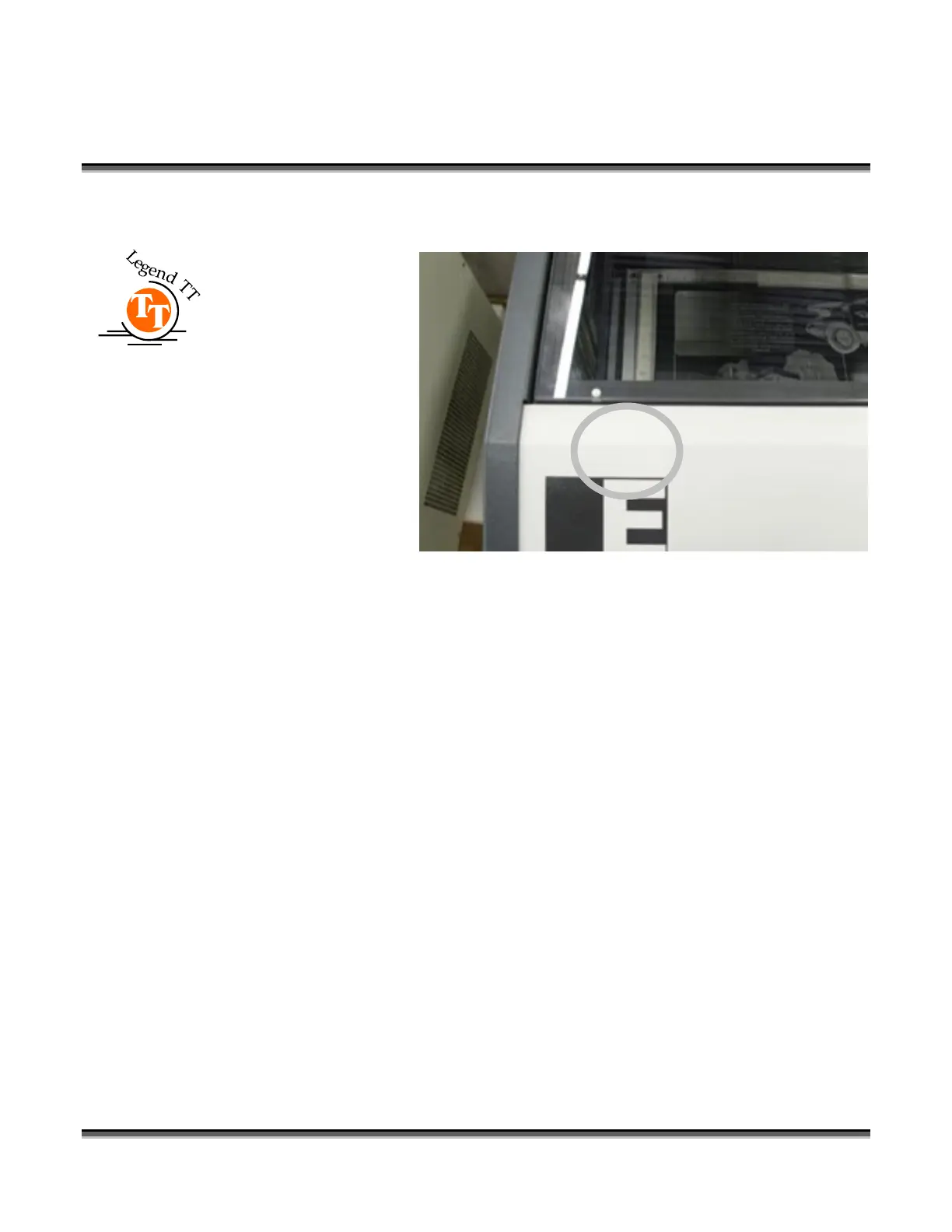
keyed connector and will only fit one way.
The Rotary connector
for the TT is located at
the front of the machine
towards the left hand
side.
Make sure the table is
lowered and the Legend
is turned off before
plugging the Rotary
Attachment into this
white connector. It is a
keyed connector and
will only fit one way.
5. The rotary attachment is now installed! Turn the power on.
6. The engraver knows that the rotary attachment is installed and changes its home
position to a point directly above the center point of the drive wheels on the
attachment.
Rotary Setup
The rotary attachment works in either raster or vector mode, and the setup is the same
for both. The part to be engraved should rest between the two sets of wheels. The
wheels on the left are the driving wheels, which spin the cylinder to be engraved. The
wheels on the right are for support. They can be raised or lowered to get the work
surface to be engraved level with the table. They can also be moved from left to right
to adjust to the length of the part being engraved. The area being engraved must be
level for the part to engrave correctly.
 Loading...