Section 15: Servicing the Legend
183
Laser Module & RF Module Legend EX
For information regarding the TT machine, please contact Technical Support. The
laser module for the Legend EX is located in the laser bay; see “SERVICE MODULE
LOCATION DIAGRAM” shown previously in this Section. To remove and/or
service this module, turn the machine off and unplug the power cord from the
machine. Remove the laser cover. The cover is secured with four or five Phillips
head screws along the lower edge of the cover. Once the cover is free, there is a
connector under the cover that you will need to disconnect before you can set the
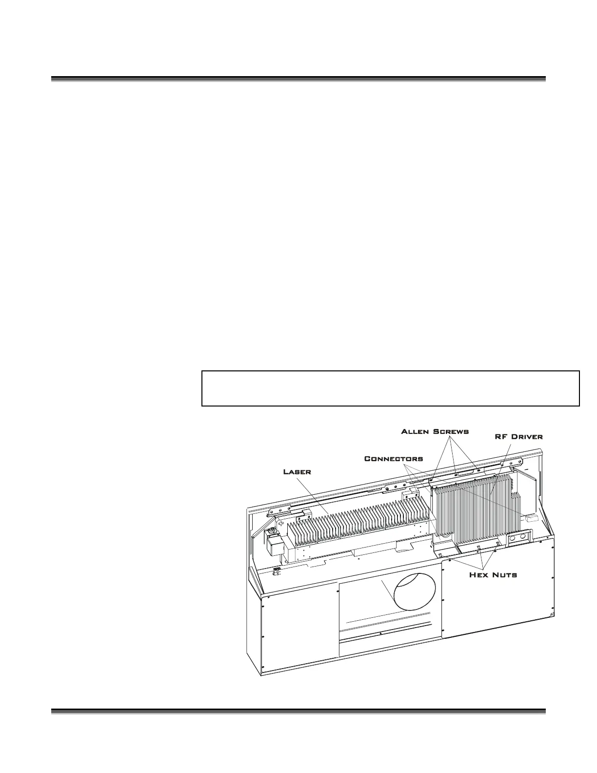
cover aside. The laser on your machine will resemble the one shown in the drawing
below. There are differences in appearance depending on the wattage of your laser
that do not effect servicing. First remove the electrical connectors, then the three
Allen head screws shown in the drawings. Once the screws are free, lift the laser off
the hangers and it should pull free (except for the RF connection, which should be
unscrewed at this time).
Some laser systems
use lasers with
separate RF drivers.
This is done for
performance
reasons to keep the
heat generated by
the RF away from
the laser itself.
50 Watt air cooled configuration
Separate Laser Tube and RF Module
 Loading...