 Loading...
Do you have a question about the Fuji Electric Frenic and is the answer not in the manual?
| Series | Frenic |
|---|---|
| Overload Capacity | 150% for 60 seconds |
| Communication Options | RS485 |
| Protection Functions | Overcurrent, Overvoltage, Undervoltage, Overheating, Short Circuit |
| Enclosure | IP20 |
| Cooling Method | Fan Cooled |
| Operating Temperature | -10°C to 50°C |
| Storage Temperature | -20°C to 65°C |
| Ambient Humidity | 5% to 95% (non-condensing) |
| Altitude | Up to 1000m |
| Output Voltage | 3-phase 230V, 3-phase 480V, 3-phase 600V, 3-phase 690V |
Presents the FRENIC Loader VG software and its purpose as an inverter support tool.
Highlights essential safety precautions to be observed when using the software and inverter.
Specifies the manual covers FRENIC Loader VG, not the inverter itself, and advises reading manuals concurrently.
Details safety precaution categories and emphasizes the risk of electric shock with RS-485 connections.
Describes the software's capabilities for remote inverter operation and function code management.
Outlines the terms and limitations of Fuji Electric's liability for the software.
Details methods for connecting inverters via USB and RS-485, including converter use.
Important notes on RS-485 connections: noise suppression, multi-drop addressing, and avoiding shared ports.
Illustrates the physical setup for a USB connection between the inverter and PC.
Provides specifications like transmission speed and wiring length, and notes on one-to-one connections.
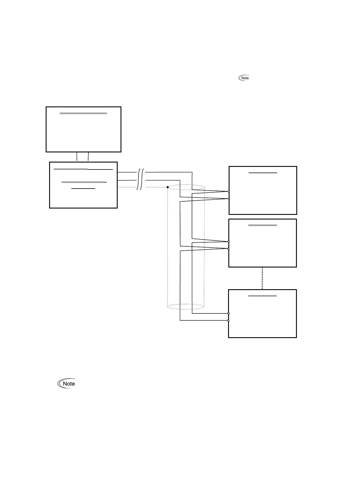
Shows a typical RS-485 multi-drop network configuration with internal termination resistors.
Advises on selecting devices for noise protection and compatibility with other inverter series.
Details on equipment needed for PCs lacking an RS-485 interface, referencing the inverter manual.
Explains methods like using ferrite cores to suppress noise and improve network immunity.
Lists requirements before installation: OS compatibility, disk space, and closing applications.
Identifies the need to install both FRENIC Loader VG and Message Manager setup files.
Walks through the installation process using screenshots for Windows 7 and Vista.
Provides detailed instructions and visual aids for installing the software on Windows XP.
Guides users through the installation process of the Message Manager component.
Detailed steps to install the USB driver on Windows 7 via Device Manager.
Procedure to install the USB driver on Windows Vista using the Found New Hardware wizard.
Step-by-step instructions for installing the USB driver on Windows XP.
How to confirm successful USB driver installation by checking Device Manager.
Procedure to uninstall FRENIC Loader VG from Windows 7 and Windows Vista.
Instructions for removing FRENIC Loader VG from Windows XP.
Steps to properly exit the Message Manager before proceeding with uninstallation.
Procedure to uninstall Message Manager from Windows 7 and Windows Vista.
Details on configuring function codes H31 (Station address), H34 (Baud rate), and H40 (Protocol) for RS-485.
Procedure to locate and verify assigned COM port numbers in Device Manager.
Steps to launch the FRENIC Loader software after installation.
Instructions for entering the password required on the first launch of the loader.
Overview of the Quick Access Menu for program shortcuts and function access.
Guide to configuring communication parameters necessary for initial inverter interaction.
Choosing connection types: direct to inverter, via MICREX-SX, or via MICREX E-SX.
Setting the SX bus address or E-SX bus address for controller communication.
Details on RS-485 port selection, baud rate, flow control, data length, parity, and stop bits.
Configuration for USB connections and communication boards (Ethernet) including type and port.
Adjusting retry count and timeout values to ensure reliable communication.
Using the Connection Check function to monitor and confirm PC-inverter communication status.
Steps to configure and monitor the link status for USB connections.
Understanding status messages like Unknown, Connecting, and Disconnected for link status.
Managing the list of inverters for RS-485 communication, including adding and deleting devices.
Setting specific equipment names and RS-485 addresses in the advanced dialog.
Configuring and monitoring the communication link status for Ethernet connections.
Description of the main window layout including Menu, Toolbar, and Status Bar.
How to create new function code data files and open existing ones.
Procedures for saving current settings and closing active windows.
Options and settings for printing function code data.
Using Print Preview and Page Setup to prepare printouts.
How to properly close and exit the FRENIC Loader software.
Navigating through the menu structure to access the Function Code Setting dialog.
Displays function codes categorized by group, changes, failure status, user definition, etc.
Core operations available: Read, Write, Factory-set, Save, Print, and Compare.
Procedure to retrieve function code settings from a connected inverter.
Methods to write edited function codes to the inverter, including editing only or all data.
How to edit numeric values for function codes using the Set Values dialog.
How to change code data values using selection menus for specific function codes.
Instructions on how to save the current function code settings.
Details on file formats like *.FN1 (Loader specific) and *.CSV (Excel compatible).
Settings for printer selection, print range, and number of copies.
Method to print only function code numbers and values using simple printing settings.
Options to compare data with inverter, file, including ReadOnly and Communication codes.
Process to select and assign function codes to User Definition groups 1 through 5.
Steps to remove individual or all function codes from user-defined groups.
How to rename User Definition groups for better organization.
Process to send user-defined limited function codes to the inverter display.
How to search for function codes by entering keywords in the search dialog.
Automatically measures motor constants and saves them to the inverter.
How to select tuning operations, monitor progress, and interpret tuning results.
View and change file information like model, region spec, capacity, and definition file.
How to adapt function code data for different inverter models (VG7 to VG1).
Modifying the inverter capacity parameter within the current function code list.
Understanding the relationship between definition files and inverter ROM versions for data compatibility.
Procedure to select the correct definition file that matches the inverter's ROM version.
How to read safety function codes, similar to standard function code reading.
Steps to unlock the functional safety password to enable writing safety function codes.
Procedure for writing safety function codes after unlocking the password.
How to save safety function codes to the card for persistence when power is off.
Procedure to change the functional safety password, requiring unlocking and new password entry.
How to initialize safety function codes to their default settings.
Introduction to Trace Back, Real-time trace, and Historical trace for analyzing inverter operation.
Description of the Trace Back window elements, including sub-windows and display areas.
Steps to read saved waveform data from the inverter's memory.
How to retrieve function code settings associated with saved trace back data.
Description of the Real-time trace window and its monitoring capabilities.
Overview of the Historical trace window for analyzing past events with triggers.
How to start and stop trace monitoring using the START/STOP button.
Procedure for saving trace data in various formats like *.TB1, *.RT1, *.HT1, *.CSV, *.JPG.
How to copy the trace data screen to the clipboard for use in other documents.
Instructions on how to print the current trace data screen.
Displays channel setting values or status at each cursor position.
Selecting cursor display types and monitoring cursor values on analog/digital channels.
Selecting channels and controlling visibility for graph analysis.
Modifying graph magnification and scale for optimal viewing.
Arranging Y-axis display position and scale for channels without overlap.
Customizing line colors, types, and thicknesses for channels and cursors.
Setting up which analog and digital channels to include in waveform tracing.
Configuring filters for analog channels to process waveform data.
Defining trigger settings (level, edge) for analog channels to capture specific events.
Details of analog signal items available for monitoring in real-time or trace back.
Details of analog signal items available for trace back, including speed and torque data.
Defining trigger settings (level, edge) for digital channels for event capture.
Selection options for input terminals (FWD, REV, X1-X14, RST) for monitoring.
Details for Input1 X terminal signal items, such as multistep speed selection and alarm reset.
Details for Input2 X terminal signal items, like UP/DOWN commands and PID control cancel.
Details for Input4 X terminal signal items, including inverse mode and alarm handling.
Details for Input5 X terminal signal items, such as custom signals and torque bias selection.
List of output terminal signal items available for monitoring.
Details for Output 1 Y terminal function items, like inverter running and speed detection.
Details for Output 2 Y terminal function items, including motor selection and alarm content.
Details for Output 3 Y terminal function items, such as motor warnings and load adaptive control.
Details for Output 6 Y terminal function items, including terminal errors and safety function status.
Monitors ON/OFF states of digital inputs and transistor outputs for the selected inverter.
Checks inverter ROM version, type, current setup, and maintenance information.
Displays current alarm status and running information recorded when alarms occurred.
Refers to Section 1.4.4 for detailed communication settings.
How to select the language (English or Japanese) for the FRENIC Loader.
Procedure to set the date and time of the inverter from the loader software.
How to show or hide the toolbar for quick access to functions.
Displays the running status of the inverter and program execution.
How to arrange multiple open windows in an overlapping cascade layout.
Arranging multiple windows side-by-side for simultaneous viewing.
Arranging multiple windows stacked vertically for simultaneous viewing.
Arranges icons of active windows or programs at the bottom of the Loader top window.
Displays the FRENIC Loader software version and copyright details.
Addresses common problems when the PC cannot communicate with the inverter.
Guidance for when Message Manager is not installed correctly, preventing communication.
Identifies issues arising from incorrect USB driver installation, leading to 'Unknown device'.
Procedure to install the USB driver on Windows Vista via Device Manager.
Step-by-step instructions for installing the USB driver on Windows XP.
Addresses communication problems when the USB driver is installed correctly but Message Manager is running.
Steps to restart Loader after PC standby/sleep in Windows 7 to regain USB recognition.
Steps to unplug/replug USB connector and restart Loader in Vista/XP for USB recognition.
Details on software name, supported inverters, and connection limits.
Specifications for OS, memory, hard disk, COM port, and transmission rates.