2-1
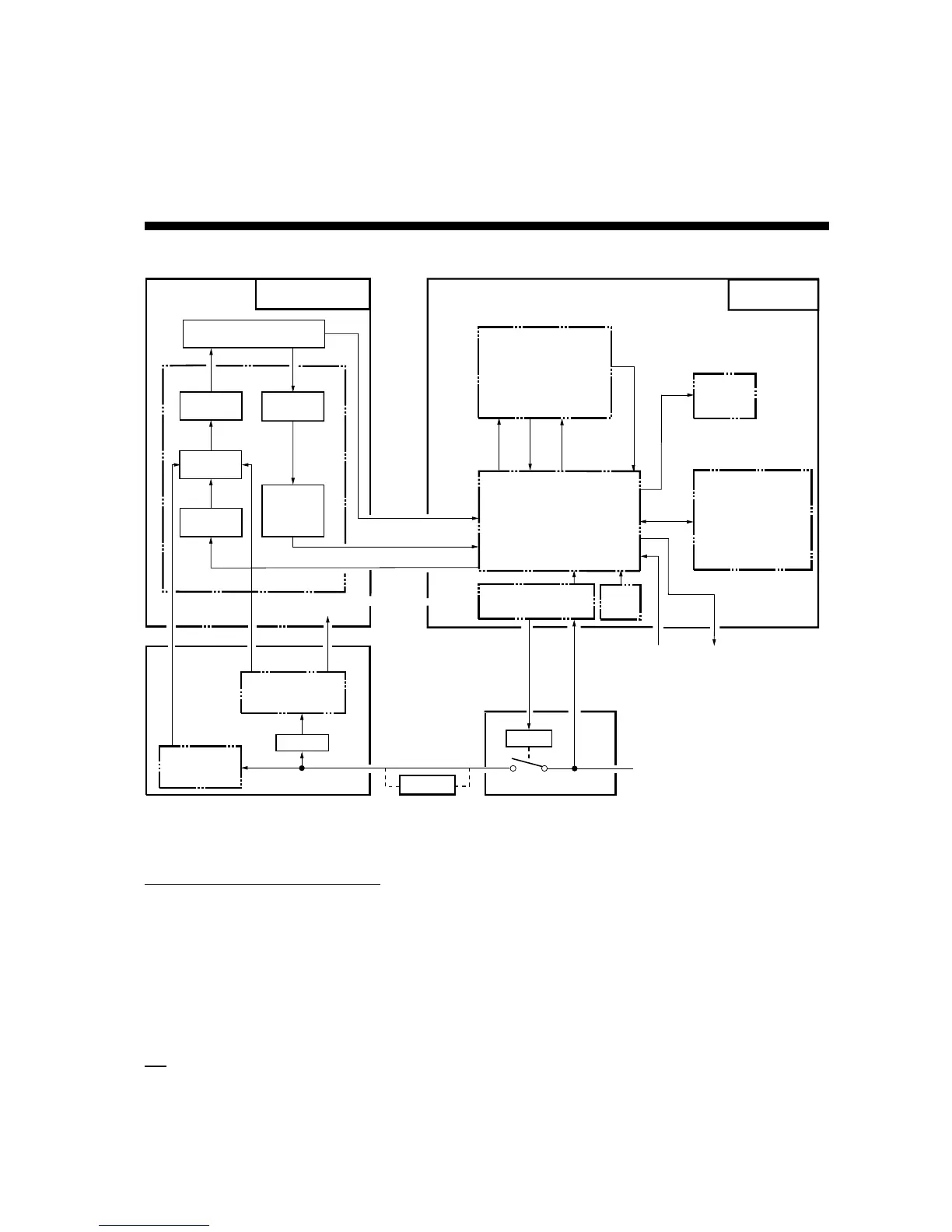
2.1 Overview
Outline
Scanner Unit
Antenna
Mag.
MIC
RFC
IF
Amp
Transceiver
Display Unit
ARP Board
(optinal)
Processor (SPU Board)
PanelPower
QV
HD, BP
Video
Trigger
HD, BP,
TRIGGER,
VIDEO
GYRO/SPEED
(NMEA or Log)
CRT
Ship's mains
(100/110/115,220/230VAC)
NAV/GYRO
Data
TTM(ARP-26)/
OSD,RSD,TLL
Mod.
TX-HV
TX-HV
RP Board
(Optional)
TTM Data
RELAY
+12V
PSU-004
PSU-001
Trans
24VAC
Power Supply Unit
+12V
-12V
Mag. Heater
RU-1758
220/230VAC
Function of Power Supply Unit
Ship’s mains is supplied to the display unit via the power supply unit PSU-001. Receiving +12 V
from the display unit, the relay in the PSU-001 is turned on and ship’s mains is supplied to the
power supply unit PSU-001 which generates TX HV, magnetron heater voltage, +12 V, and –12
V for the transceiver unit.
The input of the PSU-001 is 100, 110, or 115 VAC, so the transformer RU-1758 is required if
ship’s mains is 220 or 230 VAC.
TX
The trigger pulse from the SPU (Processor) Board is delivered to the MODULATOR Board
which outputs the signal to oscillate the magnetron, and then radar wave is emitted from the
radiator.
Chapter 2. BLOCK DESCRIPTION
Figure 2.1 Simplified block diagram
 Loading...