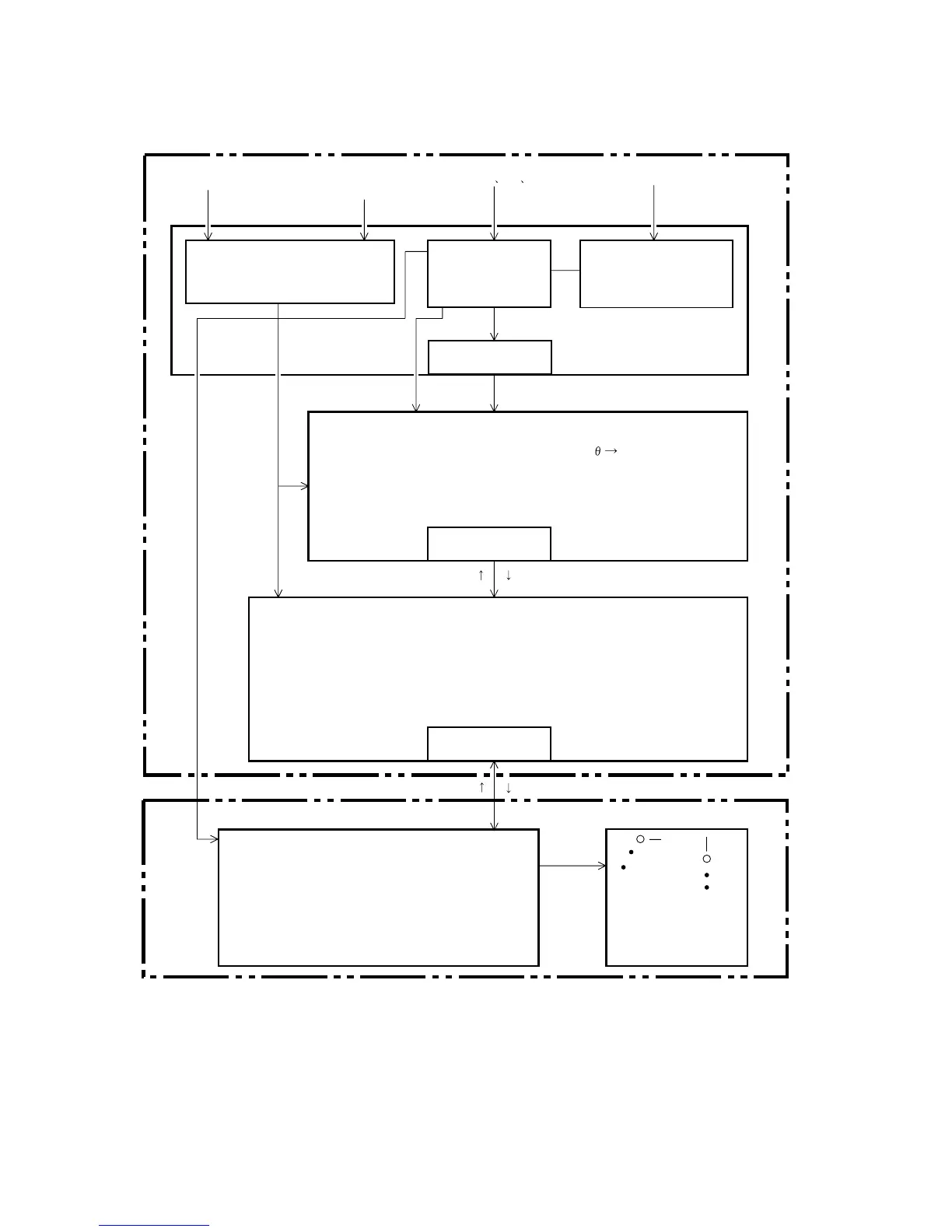
2-18
2.18 Simple ARPA block diagram
Interface for detecting amount
of position change
Echo position data
detector
A/D conversion of input
analog video signal
processed with
GAIN, STC and FTC.
D.P.RAM
Front end
processor
RADAR
(TRIG
HD BP)
RADAR
(VIDEO)
Echo data
1. Conversion of echo position coordinate (R/ X.Y)
2. Edge detection of estimated position of tracking and acquiring
echoes.
3. Error detection of input signal (TRIG, HD, BP, VIDEO, Log, Gyro.)
4. Echo detection within guard zone and auto ACQ area.
D.P.RAM
D.P.RAM
DSP (Digital Signal Processor)
BP
1. Target data of manually acquired target and automatic acquisition of target
inside guard ring.
2. Automatic tracking of target.
3. Calculation of target’s CPA/TCPA, speed and course.
4. Conversion of data to display target data.
MAIN CPU Processor
QV echo
Candidate echo detected within echo detection
window.
Echo detection window
Target data
Key command
1. Outputs acquisition and position data to ARPA
Board.
2. Processes markers for display on CRT.
3. Displays and memorizes ARPA track.
4. Checks for presence or absence of ARP
Board when power is applied.
SPU Board
CRT Display
Speed Log
(Contact signal, Nav data,
Manual speed input)
Gyrocompass
(25 msec AD format)
FR2115-SME-15
ARPA Board
SPU Board
 Loading...