2-9
J417
MOTHER Board
IF IN
03P9251
J414
1
A19
A20
A21
From RF
Unit
J444
INT Board
03P9252
P417
TP1
J458
8
TP3
R21
R134
K2
C5
VIDEO SEL
J417
about
4.5Vpp
about
4Vpp
+12V
Q18,19
Q40,41
Q37,38
Q27,28
Q10,11
Q22,26
Q8,9
Main/remote display and
Radar 1/2 selection
ARPA VIDEO
RJ7 VIDEO
OP VIDEO A
OP VIDEO B
RF VIDEO
8
15
J457
8
J442
8
J443
C21
C22
B21
P417
A19
A20
A21
Extanal radar or RJ-7
J551
MOTHER Board
IF IN
03P9251
J414
C14
External ARPA
RJ7
Slave display
Slave display
C21
C22
B21
R140
SPU Board
P551
Video Amp.
(GAIN,A/C SEA,
and A/C RAIN
Adjustment)
C14
about
4Vpp
03P9253
TP12
A18
P551
ARP Board
TP6
FR-2155-SMJ10E
about
4Vpp
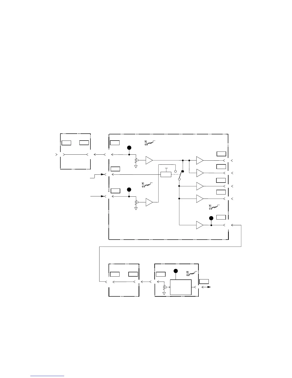
2.6 Video Signal Flow
The figure below shows video signal flow. The video signal from the scanner unit
and an external radar are adjusted in level by R21 and R134 on the INT board
03P9252 respectively so that the main bang level at TP6 on the INT board is 3.9 to
4.1 Vpp. The R140 on the SPU board is factory-adjusted so that the main bang
level is 3.9 to 4.1 Vpp at TP12.
The video signal from the SPU board to the ARP board is gain-, STC-, and A/C
sea-adjusted.
When the radar is used as a remote display, no signal is output from External
ARPA and RJ-7 ports.
Figure 2.4 Video Signal
 Loading...