4-7
4.4 Self-test
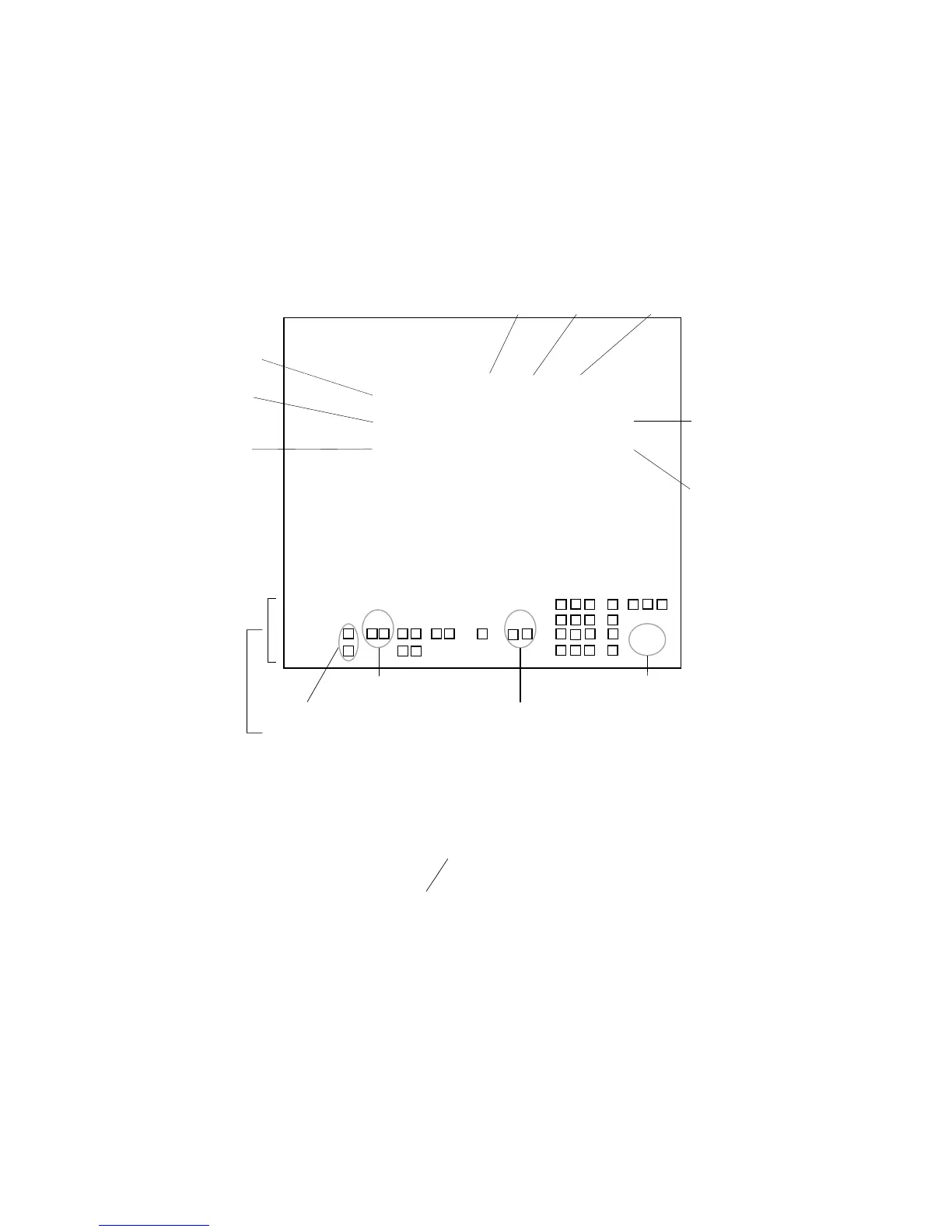
Test Menu
Press [RADAR MENU], [0], [0], [0], [3], and [ENTER] in this order, and the self-test result
display will appear after several seconds. Figure 4.2 shows the self-test result display. If any
error has been found in circuitry, NG appears instead of OK. The self-test is carried out at every
power-up, not when the keys are pressed. If the self-test detects an error, the message SYSTEM
FAIL appears at the lower right of the screen.
Figure 4.2 Self-test Result Display
FR-2105 TEST
PROGRAM NO ROM RAM CRAM DIPSW
MAIN 0359149101 OK OK 1234
ARP 1859038104 OK OK OK 0000
DSP 1859039101 OK OK OK
RP 0359150101 OK OK OK 0000
DRAM OK
RP BOARD BAT OK
RP CARD 1 OK CARD 2 OK
CARD 1 BAT OK CARD2 BAT OK
ANTENNA SPEED 0.0RPM
TRIG FREQ 0Hz
MAG CURRENT 4.9V
R. MONITOR 1.8V
TUNE IND 2.5V
ROM Test
RAM Test
CRAM Test
Radar system
program number
(MAIN board)
ARP program
number
(ARP board)
RP program
number
(RP board)
EBL test
Test for PM and Degauss switches
Key and knob test
(BRILLIANCE, A/C RAIN, A/C SEA, and GAIN knobs are not tested.)
Trackball test
251
008
002
123
VRM test
FR2115-SME-45
CH1 $GPGLL,3445.000, N, 13521.000,E <CR> <LF>
IEC61162 signal input to J450 is monitored.
DIP switch setting,
S1 on ARP board
(#1 to #4 from left)
0 : on, 1 : off
DIP switch setting,
S1 on RP board
0 : on, 1 : off
 Loading...