1-1
1.1 Outline
This manual provides the information necessary for the servicing and adjustment of the radar
FR-2155.
The antenna unit uses a Log IF amplifier.
The features are;
• Flash ROM enabling program update to use a PC
• Non-interlace, high-resolution display (1024x1280 dots)
• Radar mapping capability
(Lines and Marks can be entered without the RP board, Gyro and L/L data required)
• Display unit separable into Monitor, Control and Processor Units
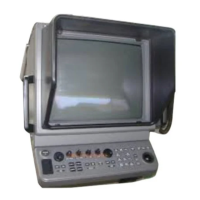
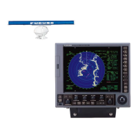
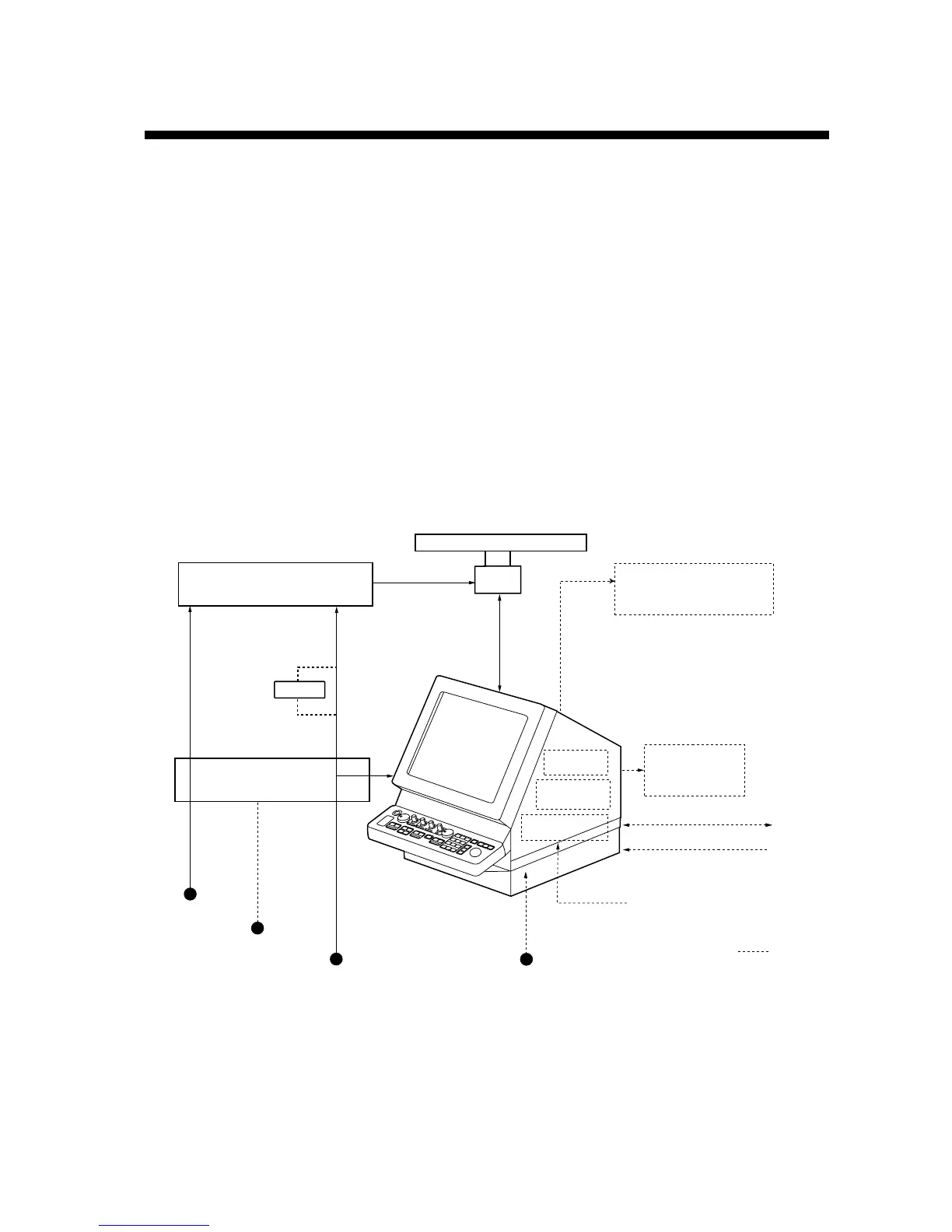
The figure shows the major configuration of FR-2155.
Display Unit
RDP-124
ARPA Board
ARP-26
NAV
IEC 61162-1(Input/Output)
IEC 61162-1(Input)
Speed Log
Option
Performance Monitor (option)
PM-30
Slave Display
SCANNER UNIT
Video Plotter
RP-26
DC24 V or
AC200/220 V, 3f,
50/60 Hz
RU-1758
AC 220/230 V
Gyro Converter
GC-8
Gyrocompass
XN-4A/XN-5A
AC100/110/115/
220/230 V
1φ, 50/60 Hz
Display Unit
AC100 V
1φ, 50/60 Hz
Power Supply unit
PSU-004
AC 110/115 V
Power Supply Unit
PSU-001
AC 110/115 V
AC100/110/115/
220/230 V
1φ, 50/60 Hz
PM-30
TX-HV, heater
±12V
De-icer
Scanner Unit
Chapter 1. GENERAL
 Loading...