4-8
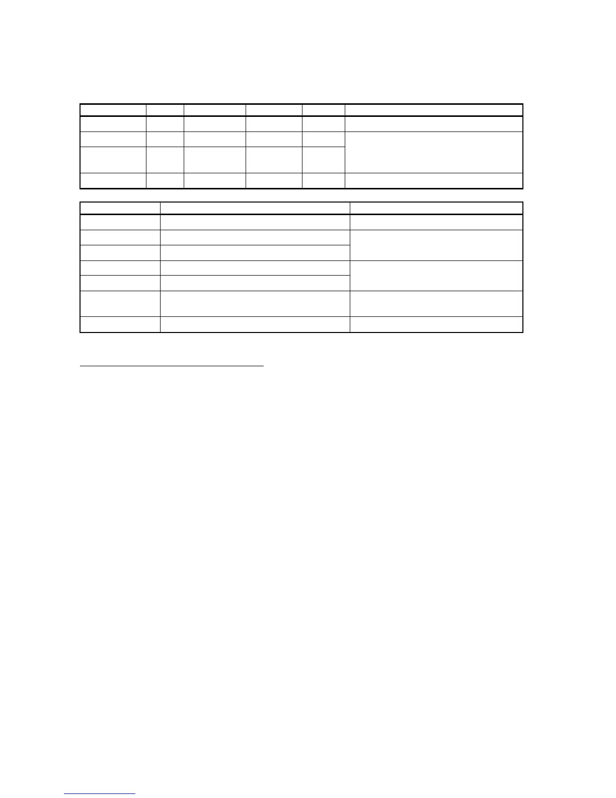
The ICs checked in the diagnostic test are shown in the table below. For “NG,” suspect faulty IC.
Note that parts level replacement is not possible; replace at board level.
Check Item ROM RAM CRAM DRAM Board to be checked
MAIN U11 U5, U7 – – 03P9253
ARP U3 U9, U10 U4, U11 –
DSP U40 U33, U36,
U38, U39
U21, U22 –
18P9002
RP U3 U8, U9 U4 U2 14P0298
Check Item Parts to be checked Remarks
RP BOARD BT Battery BT1 on 14P0298 Replace 14P0298.
RP CARD 1 Card or pcb related to upper card slot
CARD 2 Card or pcb related to lower card slot
Replace 14P0299 (CARD I/F) or
14P0298 (RP).
CARD 1 BAT Card or its battery in upper card slot
CARD 2 BAT Card or its battery in lower card slot
Replace memory card.
ANTENNA
SPEED
Refer to P2-14 Replace motor or related pcb.
TRIG FREQ Replace 03P9253.
Description of the self-test result display
1) When the ARP and RP boards are not installed, related lines are shown by Xs.
2) RAM card will be NG if the card is inserted after power-up.
3) RP BOARD BAT: Checks the voltage of the battery on the RP board. NG will appear when
the battery drops to less than 2.65 V. The capacity of a new battery is about 3.6 V.
4) CARD1 BAT/CARD 2 BAT: The capacity of the battery inside the card is checked.
5) ANTENNA SPEED: Set the radar to TX. 0 (zero) is indicated in STBY mode.
6) TRIG FREQ: Set the radar to TX and stop the antenna rotation.
7) MAG CURRENT*: Reference only. The value is not actual magnetron current. If the radar
is normal, the value increases when the radar is set from STBY to TX.
8) R. MONITOR* Reference only. This checks regulated +5 V for MIC. If 0 V, it is abnormal.
9) TUNE IND*: Reference only. If the radar is normal, the value increases when the radar is
set from STBY to TX. The defective magnetron or MIC is expected if the value is low at
TX.
10) *: Service call with these readings may help the technician to prepare necessary spare parts.
Keyboard Test
Pressing a key highlights the corresponding location on the display screen.
The STBY TX key is pressed in the end.
 Loading...