2-33
2.31 Block Diagram of MD Board (03P6666)
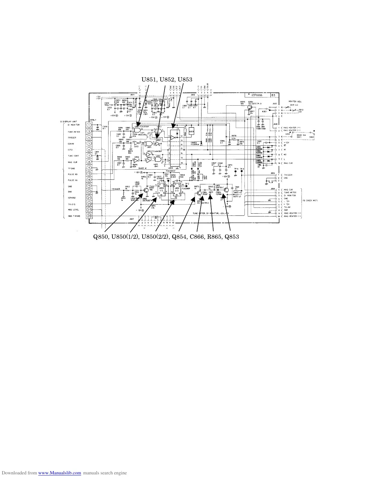
The MODULATOR TRIGGER Board PFN(1) (03P6668), generates pulses that fire the modula-
tor SCRs (CR813/CR814/CR815).
Normally the circuit is stable with Q850/Q853 off. Q850 turns on upon receiving the TX trigger
from the display unit and generates a negative going pulses at its collector. A positive going pul-
se is produced at pin #6 of U850 (1/2) and sent to Q854, and then a negative going pulse is gen-
erated at the collector of Q854. The negative going pulse is differentiated by C866 and R865,
and then only a negative going differentiated waveform is applied to the base of Q853. As a re-
sult, a positive going pulse (Modulator Trigger Pulse) is produced at the collector of Q853 and
delivered to the modulator SCR.
Figure 2.15 MODULATOR TRIGGER Board (03P6666)
Q850, U850(1/2), U850(2/2), Q854, C866, R865, Q853
U851, U852, U853
 Loading...