GE HEALTHCARE
D
IRECTION 5141177-100, REVISION 14 BRIGHTSPEED ELITE, EDGE, EXCEL: PRE-INSTALLATION
Page 130 Section 3.0 - Recommended Power Distribution System
Section 3.0
Recommended Power Distribution System
A dedicated feeder run from the facility main isolation transformer is recommended to power the
BrightSpeed CT scanner. If the scanner must be powered from an existing distribution transformer
and secondary feeder, such as the equipment distribution panel of an X-ray department, installation
with other X-Ray equipment that use rapid film changers should be avoided. These changers use
a large number of high powered, closely spaced exposures, which may coincide with the CT scan
and produce image artifacts.
IF THE POWER FEED FOR THE A1/PDB PANEL IS NOT ON A DEDICATED
POWER TRANSFORMER ANY DEVICE THAT SHARES POWER FROM THAT
TRANSFORMER MAY BE IMPACTED BY INADVERTENT POWER
INTERUPTION CAUSED BY AN A1/PDB POWER PANEL FAULT.
CONVERSLY, THE OPERATION OF OTHER DEVICES SHARING THE POWER
TRANSFORMER MAY ALSO IMPACT THE OPERATION OF THE CT/PET
SCANNER.
If a dedicated distribution transformer is provided for the scanner, the minimum recommended
transformer size is 112.5 kVA, rated 2.4% regulation at unity power factor. For this configuration,
the minimum recommended feeder size and overcurrent protection device based on line voltage is
shown in Table 8-2 Minimum Feeder Wire Size.
In all cases, qualified personnel must verify that the transformer and feeder, at point of take-off, plus
the run to the BrightSpeed CT scanner meet all the requirements stated in this document.
SYSTEM CHARACTERISTICS:
Note: (xxx):The value in the brackets is for 75kVA.
• Maximum power demand = 90kVA (75kVA) @ 0.85 PF: at a Selected Technique of 140 kV,
380 mA (300mA).
• Continuous (average) power demand at maximum duty cycle = 20kVA (16.7kVA).
• Maximum allowable total source regulation is 6%.
• Minimum recommended transformer size: 112.5 kVA (93.75kVA), with 2.4% rated regulation
at unity power factor. Resultant maximum allowable feeder regulation is 3.4%.
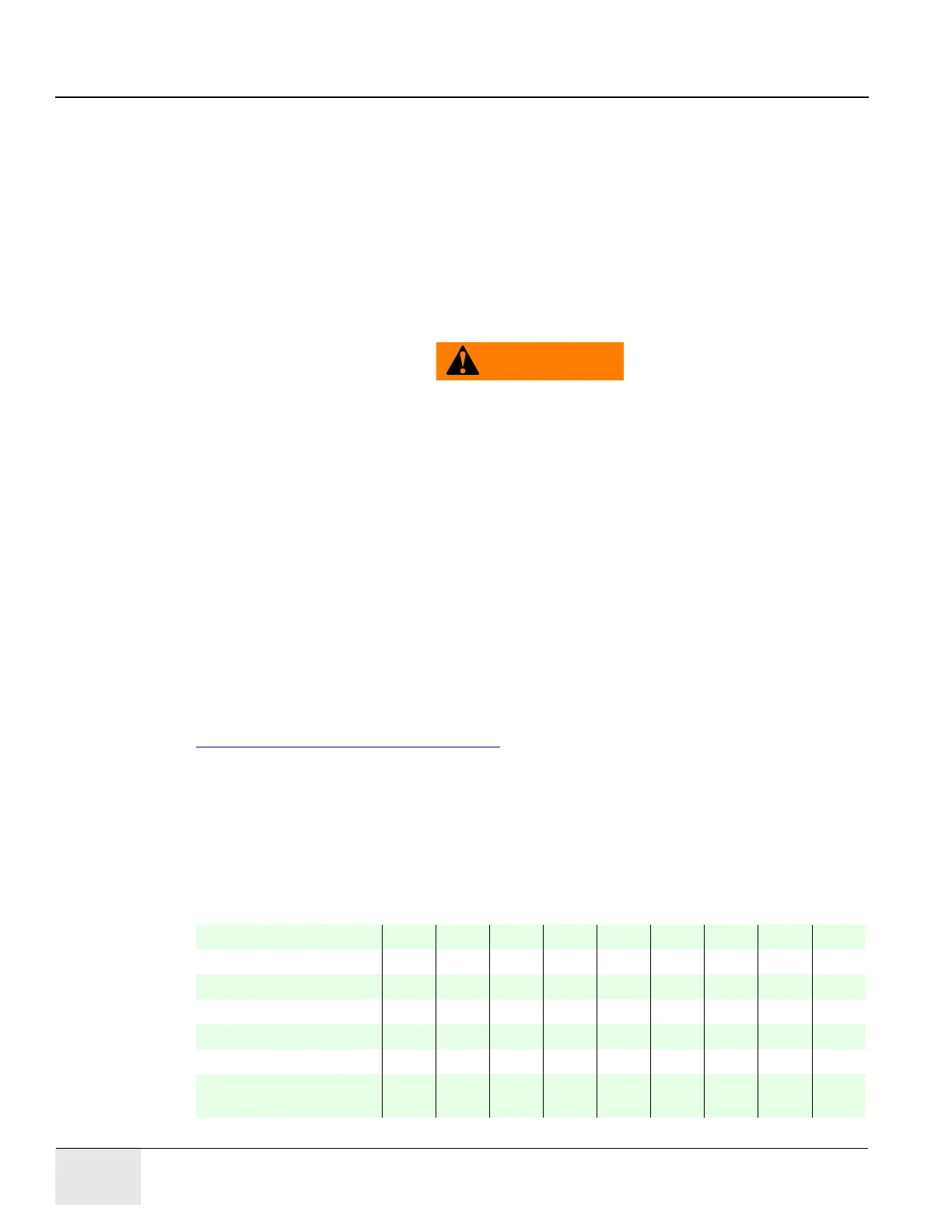
The nominal line voltage must fall within one of the ranges listed below
Nominal Line Voltage 200 220 240 380 400 420 440 460 480
Hi-Line Limit, +10% 220 242 264 418 440 462 484 506 528
Lo-Line Limit, -10% 180 198 216 342 360 378 396 414 432
Continuous Line Current585248302927262524
Momentary Line Current 260 236 217 137 130 124 118 113 108
Maximum Line Current 289 262 241 152 144 137 131 126 120
Minimum Recommended
Circuit Protection Rating
150 150 150 110 110 100 100 90 90
Table 8-1 Nominal Line Voltage

 Loading...