GE HEALTHCARE
D
IRECTION 5141177-100, REVISION 14 BRIGHTSPEED ELITE, EDGE, EXCEL: PRE-INSTALLATION
Chapter 4 - Room Planning Page 83
4 – Room Planning
Section 7.0
Minimum Dimensions and Clearances
7.1 Options
Ceiling Pedestal mount lowest point to floor (Injector or Monitor) 2134.0 mm (84.0 in)
7.2 System Operation
7.3 Injector Control
A suitable work area, which is within reach of the operator's console, should be provided for
placement of the injector control.
Wall mounted, ceiling mounted and pedestal units need cables to be routed from the gantry area to
the console area. Injectors AC power is supplied with Accessory I/F hardware kit.
Note: Injector cables should not be routed with the system cables.
Mounts are available in different configurations and lengths. Refer to Injector documentation for
detailed installation instructions.
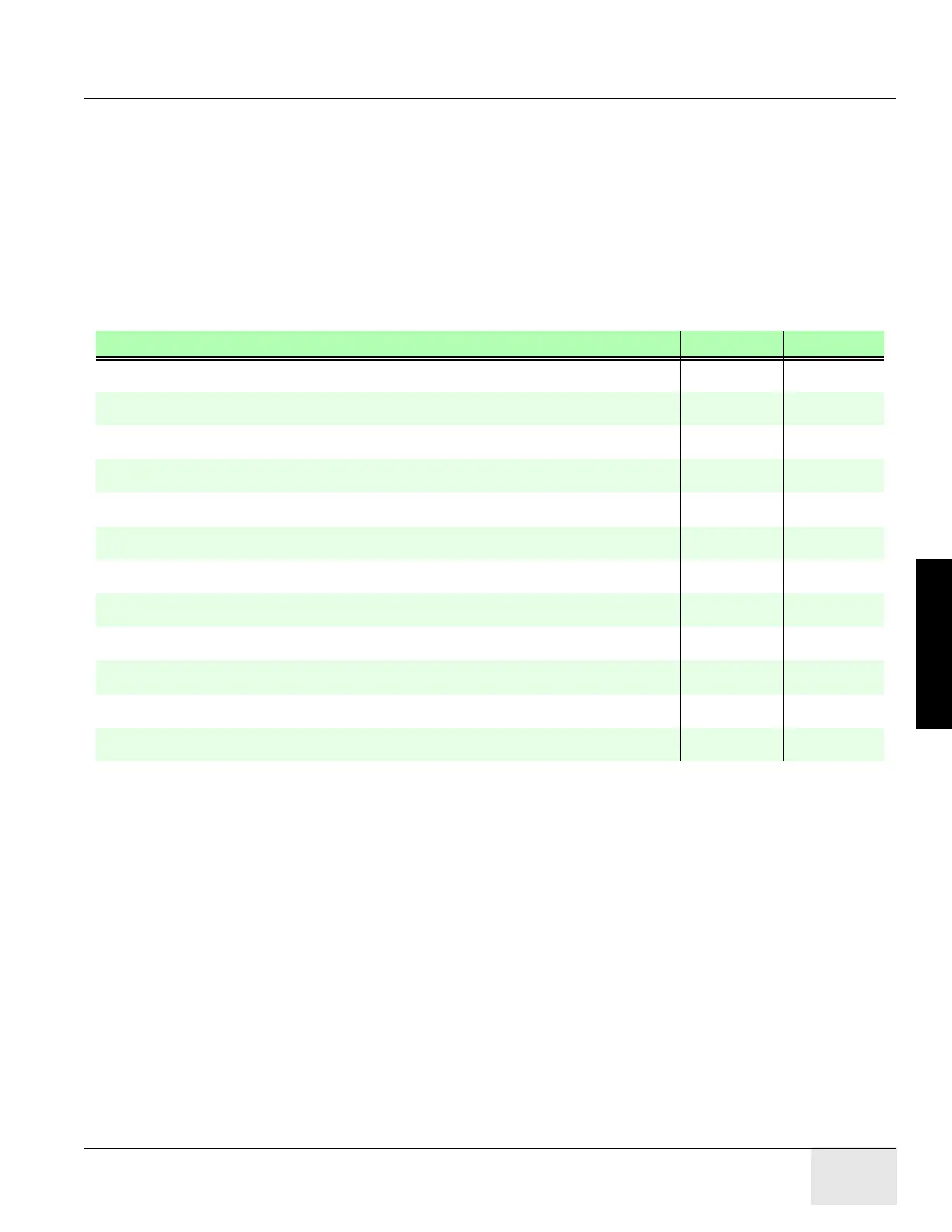
SYSTEM OPERATION MM INCHES
Finished ceiling to floor (recommended) 2743.0mm 108.0 in.
Finished ceiling to floor (minimum) 2286.0mm 90.0 in.
HPower Table max extension head end w/extender from Center Line 2030.0mm 80.0 in.
HPower Table extension head end w/extender to obstruction 152.0mm 6.0 in.
HPower Table in lowest pos. w/cradle @home pos. to Center Line 3209.0mm 126.5 in.
GT1700 Table max extension head end w/extender from Center Line 1712.0 mm 67.0 in.
GT1700 Table extension head end w/extender to obstruction 150.0 mm 6.0 in.
GT1700 Table in lowest pos. w/cradle @home pos. to Center Line 3209.0 mm 126.5 in.
GT1700 Table in lowest pos. w/cradle @home pos. to surface of Gantry front cover 2744.0 mm 108.0 in.
Back of GOC4/LCGOC/AIO Console to wall 152.0mm 6.0 in.
Back of TIO/NIO16 Console to wall 96.0mm 4.0 in.
Back of PDU to wall 152.0mm 6.0 in.

 Loading...