GE HEALTHCARE
D
IRECTION 5141177-100, REVISION 14 BRIGHTSPEED ELITE, EDGE, EXCEL: PRE-INSTALLATION
Page 132 Section 4.0 - Ground System
Section 4.0
Ground System
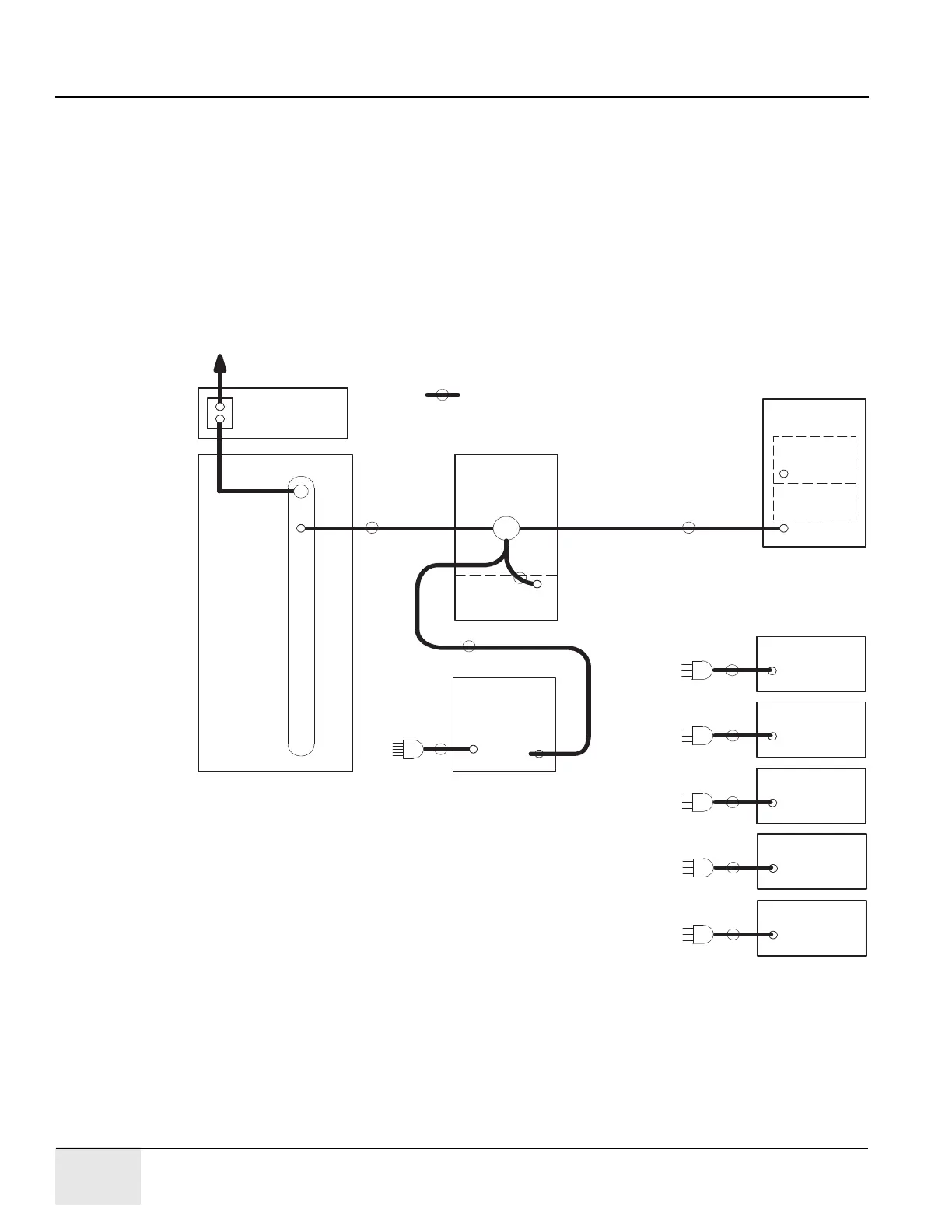
The BrightSpeed CT Scanner has been designed to use an equal potential grounding system. The
required ground system is shown in Figure 8-1. There are three primary grounding points:
• A system power ground point located in the PDU.
• A reference ground point located between gantry and table base.
• A patient ground point located at the front of the table base.
All exposed metal surfaces in the patient vicinity are grounded to the reference ground point.
For additional information, refer to Electrical Safety Equipment, Direction 46-014505.
Figure 8-1 System Ground Map
CON SOLE/
(OC1)
#1/0
G
TABLE/GANTRY
JUNCTION
RACEWAY
TABLE
(CT1)
NOTES:
SHIELD / SIGNAL GROUNDS ARE NOT SHOWN.
=GROUND WIRE IN SUPPLIED CABLE.
DISK UNITS ARE LOCATED IN
CC1 AND SCU.
OPERATOR'S
#2
POWER
DISTRIBUTION
UNIT
GANTRY
FRAME
TILT
ROTATING
ASSEMBLY
(CT2)
#1/0
#2
MECH
FRAME
(PM)
T
IN-ROOM
MONITOR
(OPTION)
TO CONSOLE
(OC1)
#1/0
PartofGantry
A1
POWER
DISCONNECT
TO POWER VAULT GROUND
VIDEO PRINTER
COLOR
(OPTION)
TO CONSOLE
(OC1)
COMPUTER
INJECTOR
(OPTION)
TO CONSOLE
(OC1)
EKG MONITOR
(OPTION)
TO GANTRY
(CT2)
RESPIRATORY
MONITOR
(OPTION)
TO GANTRY
or CONSOLE

 Loading...