GE HEALTHCARE
D
IRECTION 5141177-100, REVISION 14 BRIGHTSPEED ELITE, EDGE, EXCEL: PRE-INSTALLATION
Chapter 9 - Interconnection Data Page 149
9 – Interconnects
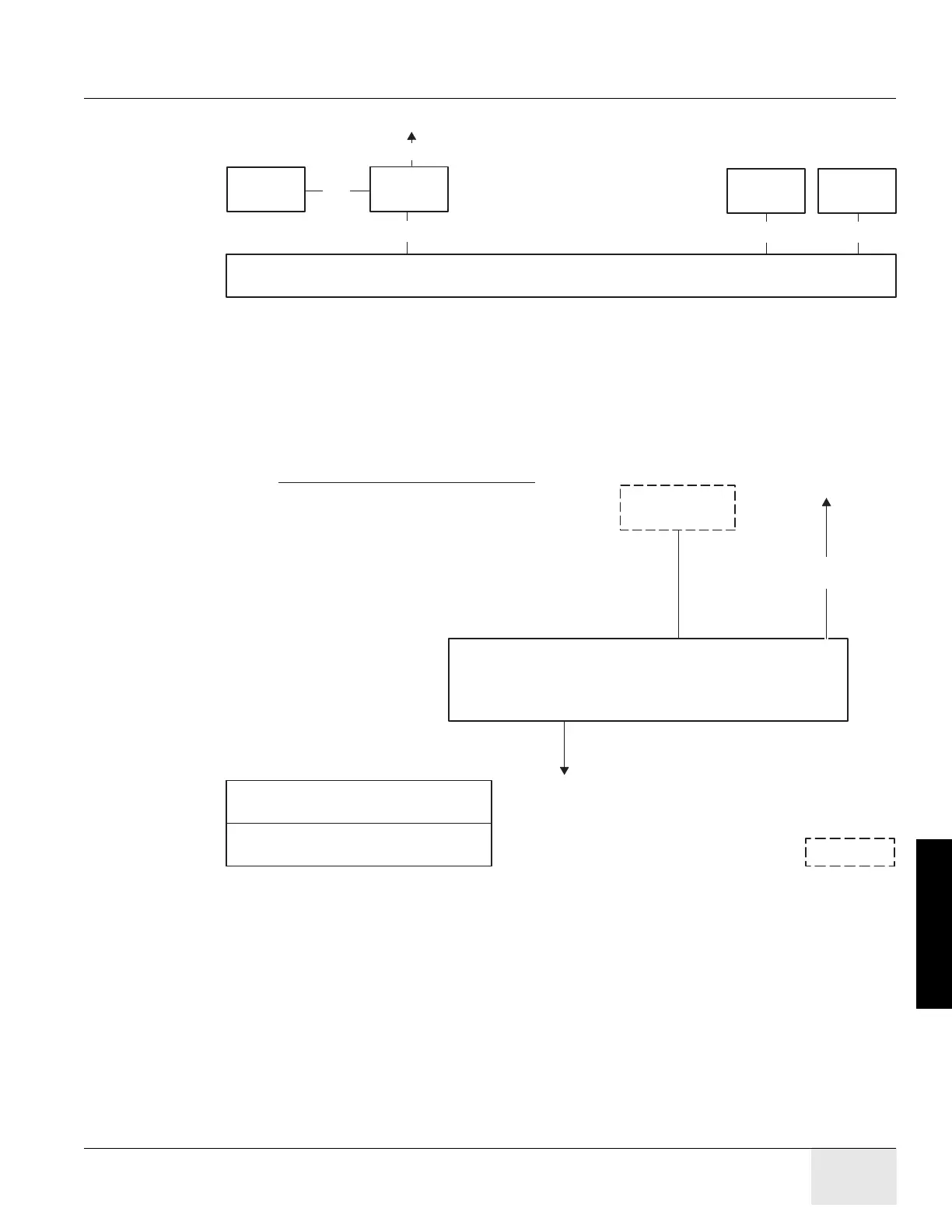
Figure 9-5 Interconnection Runs
TO POWER
SOURCE
GANTRY
(CT2)
TABLE
(CT1)
OPERATORS CONSOLE/COMPUTER
(OC1)
PM
(PDU)
WL
1
SEO
A1
3
4
TO
ETHERNET
Broadband
Network
(see Note 3)
2
Laser Imager Option
(see Note 2)
DS
Only one phone connection
is required for the system.
5
10
OPTION
KEY:
TO
TELEPHONE
SYSTEM
(see Note 1)
NOTES:
1) Used for remote diagnostics - Option
2) Refer to the appropriate Pre-installation / Installation
documents for the Laser Camera
3) Category 5 cable. Use one of the following patch cords:
CAT Num GE Part Num Length
K9000WB 2215028-10 20 m
K9000KP 2215028-5 10 m
K9000JR 2215028-4 5 m
K9000WA 2215028-9 3 m
4) In order to avoid any violation of each National Regulation
(NEC in USA, CCC in China, etc.), use of the complied
cable/wire is recommended. For China market, China end-user
shall purchase the power supply cable that has the CCC mark.

 Loading...