3-38 L30 Line Current Differential System GE Multilin
3.3 PILOT CHANNEL COMMUNICATIONS 3 HARDWARE
3
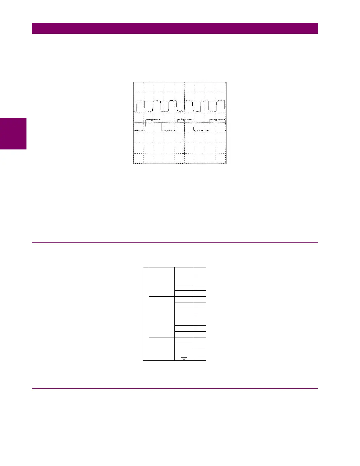
c) TRANSMIT TIMING
The RS422 interface accepts one clock input for transmit timing. It is important that the rising edge of the 64 kHz transmit
timing clock of the multiplexer interface is sampling the data in the center of the transmit data window. Therefore, it is impor-
tant to confirm clock and data transitions to ensure proper system operation. For example, the following figure shows the
positive edge of the Tx clock in the center of the Tx data bit.
Figure 3–40: CLOCK AND DATA TRANSITIONS
d) RECEIVE TIMING
The RS422 interface utilizes NRZI-MARK modulation code and; therefore, does not rely on an Rx clock to recapture data.
NRZI-MARK is an edge-type, invertible, self-clocking code.
To recover the Rx clock from the data-stream, an integrated DPLL (digital phase lock loop) circuit is utilized. The DPLL is
driven by an internal clock, which is 16-times over-sampled, and uses this clock along with the data-stream to generate a
data clock that can be used as the SCC (serial communication controller) receive clock.
3.3.6 TWO-CHANNEL TWO-CLOCK RS422 INTERFACE
The two-channel two-clock RS422 interface (module 7V) is for use with the synchrophasor feature. The figure shows the
module connections.
Figure 3–41: TWO-CHANNEL TWO-CLOCK RS422 INTERFACE CONNECTIONS
3.3.7 RS422 AND FIBER INTERFACE
The following figure shows the combined RS422 plus fiberoptic interface configuration at 64K baud. The 7L, 7M, 7N, 7P,
and 74 modules are used in two-terminal with a redundant channel or three-terminal configurations where channel 1 is
employed via the RS422 interface (possibly with a multiplexer) and channel 2 via direct fiber.
831733A1.CDR
Tx Clock
Tx Data
842802A2.CDR
~7b
~8a
7V
Shield
Rx +
Tx –
Rx –
Tx –
Tx +
Rx –
Shield
Rx +
Tx +
RS422 communications
~4b
~5b
~4a
~3a
~3b
~6a
~5a
~6b
~2a
RS422
channel 2
RS422
channel 1
Surge
Tx –
Rx –
~7a
~8b
Channel 1
clock
Common
~2b
COM
Tx –
Rx –
~1b
~1a
Channel 2
clock
 Loading...


