GE Multilin L30 Line Current Differential System 1-9
1 GETTING STARTED 1.3 ENERVISTA UR SETUP SOFTWARE
1
1.3.4 USING THE QUICK CONNECT FEATURE
a) USING QUICK CONNECT VIA THE FRONT PANEL RS232 PORT
Before starting, verify that the serial cable is properly connected from the computer to the front panel RS232 port with a
straight-through 9-pin to 9-pin RS232 cable.
1. Verify that the latest version of the EnerVista UR Setup software is installed (available from the GE EnerVista CD or
online from http://www.gegridsolutions.com/multilin
). See the Software Installation section if not already installed.
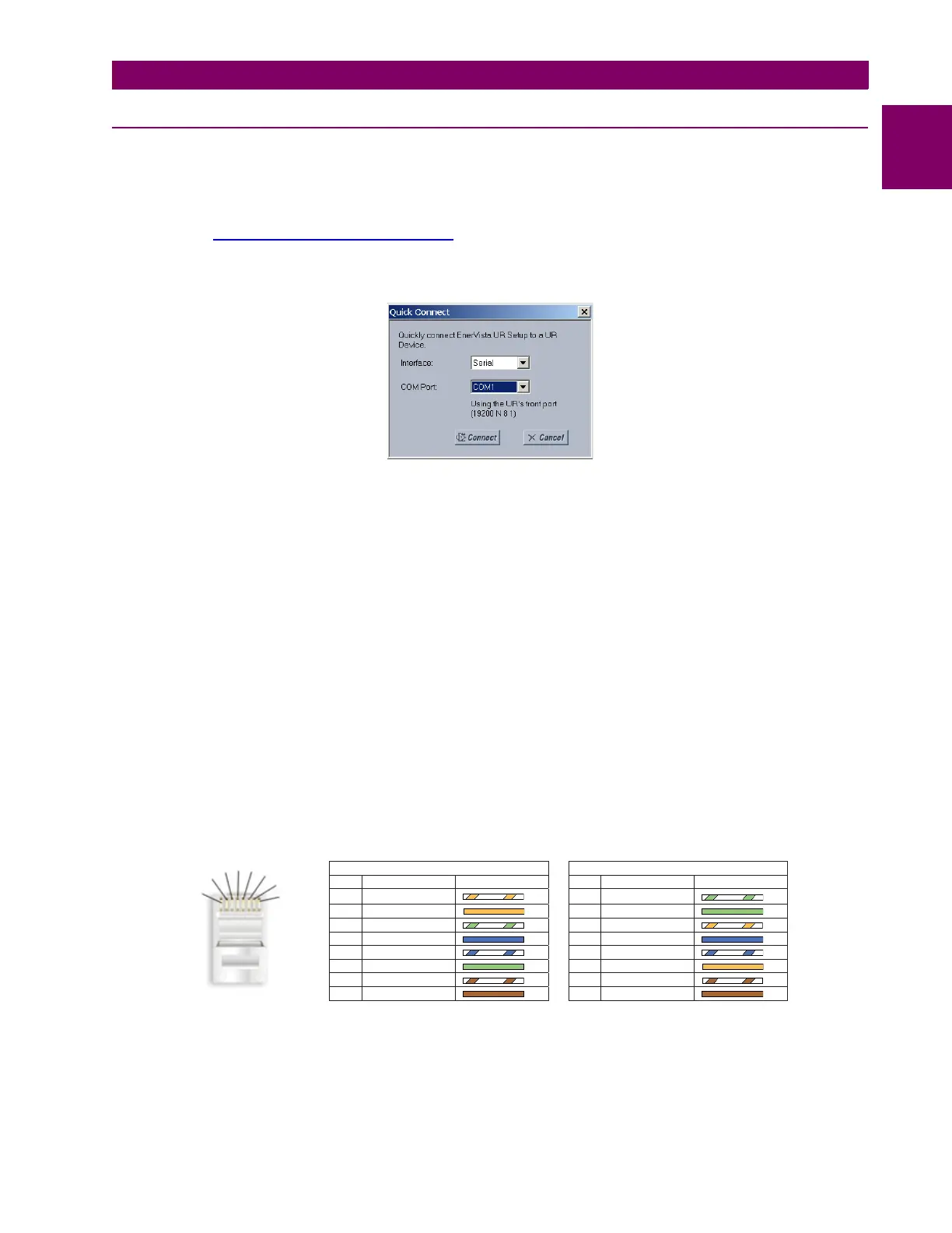
2. Select the “UR” device from the EnerVista Launchpad to start EnerVista UR Setup.
3. Click the Quick Connect button to open the Quick Connect dialog box.
4. Select the Serial interface and the correct COM Port, then click Connect.
5. The EnerVista UR Setup software creates a site named “Quick Connect” with a corresponding device also named
“Quick Connect” and displays them at the upper-left of the screen. Expand the sections to view data directly from the
L30 device.
Each time that the EnerVista UR Setup software is initialized, click the Quick Connect button to establish direct communi-
cations to the L30 device. This ensures that configuration of the EnerVista UR Setup software matches the L30 model num-
ber.
b) USING QUICK CONNECT VIA THE REAR ETHERNET PORTS
To use the Quick Connect feature to access the L30 from a computer through Ethernet, first assign an IP address to the
relay from the front panel keyboard.
1. Press the MENU key until the SETTINGS menu displays.
2. Navigate to the
SETTINGS PRODUCT SETUP COMMUNICATIONS NETWORK IP ADDRESS setting.
3. Enter an IP address, for example “1.1.1.1,” and select the ENTER key to save the value.
4. In the same menu, select the
SUBNET IP MASK setting.
5. Enter a subnet IP address, for example “255.0.0.0,” and press the ENTER key to save the value.
Next, use an Ethernet cross-over cable to connect the computer to the rear Ethernet port. In case you need it, the figure
shows the pinout for an Ethernet cross-over cable.
Figure 1–8: ETHERNET CROSS-OVER CABLE PIN LAYOUT
Now, assign the computer an IP address compatible with the relay’s IP address.
842799A1.CDR
END 1 END 2
Pin Wire color Diagram Pin Wire color Diagram
1 White/orange 1 White/green
2 Orange 2 Green
3 White/green 3 White/orange
4 Blue 4 Blue
5 White/blue 5 White/blue
6 Green 6 Orange
7 White/brown 7 White/brown
8 Brown 8 Brown
1
2
3
4
5
6
7
8
 Loading...


