GE Multilin L30 Line Current Differential System 5-217
5 SETTINGS 5.7 CONTROL ELEMENTS
5
5.7.5 UNDERFREQUENCY (ANSI 81U)
PATH: SETTINGS CONTROL ELEMENTS UNDERFREQUENCY UNDERFREQUENCY 1(6)
There are six identical underfrequency elements, numbered from 1 through 6.
The steady-state frequency of a power system is a certain indicator of the existing balance between the generated power
and the load. Whenever this balance is disrupted through the loss of an important generating unit or the isolation of part of
the system from the rest of the system, the effect will be a reduction in frequency. If the control systems of the system gen-
erators do not respond fast enough, the system may collapse. A reliable method to quickly restore the balance between
load and generation is to automatically disconnect selected loads, based on the actual system frequency. This technique,
called “load-shedding”, maintains system integrity and minimize widespread outages. After the frequency returns to normal,
the load may be automatically or manually restored.
The
UNDERFREQ 1 SOURCE setting is used to select the source for the signal to be measured. The element first checks for a
live phase voltage available from the selected source. If voltage is not available, the element attempts to use a phase cur-
rent. If neither voltage nor current is available, the element will not operate, as it will not measure a parameter below the
minimum voltage/current setting.
The
UNDERFREQ 1 MIN VOLT/AMP setting selects the minimum per unit voltage or current level required to allow the underfre-
quency element to operate. This threshold is used to prevent an incorrect operation because there is no signal to measure.
This
UNDERFREQ 1 PICKUP setting is used to select the level at which the underfrequency element is to pickup. For example,
if the system frequency is 60 Hz and the load shedding is required at 59.5 Hz, the setting will be 59.50 Hz.
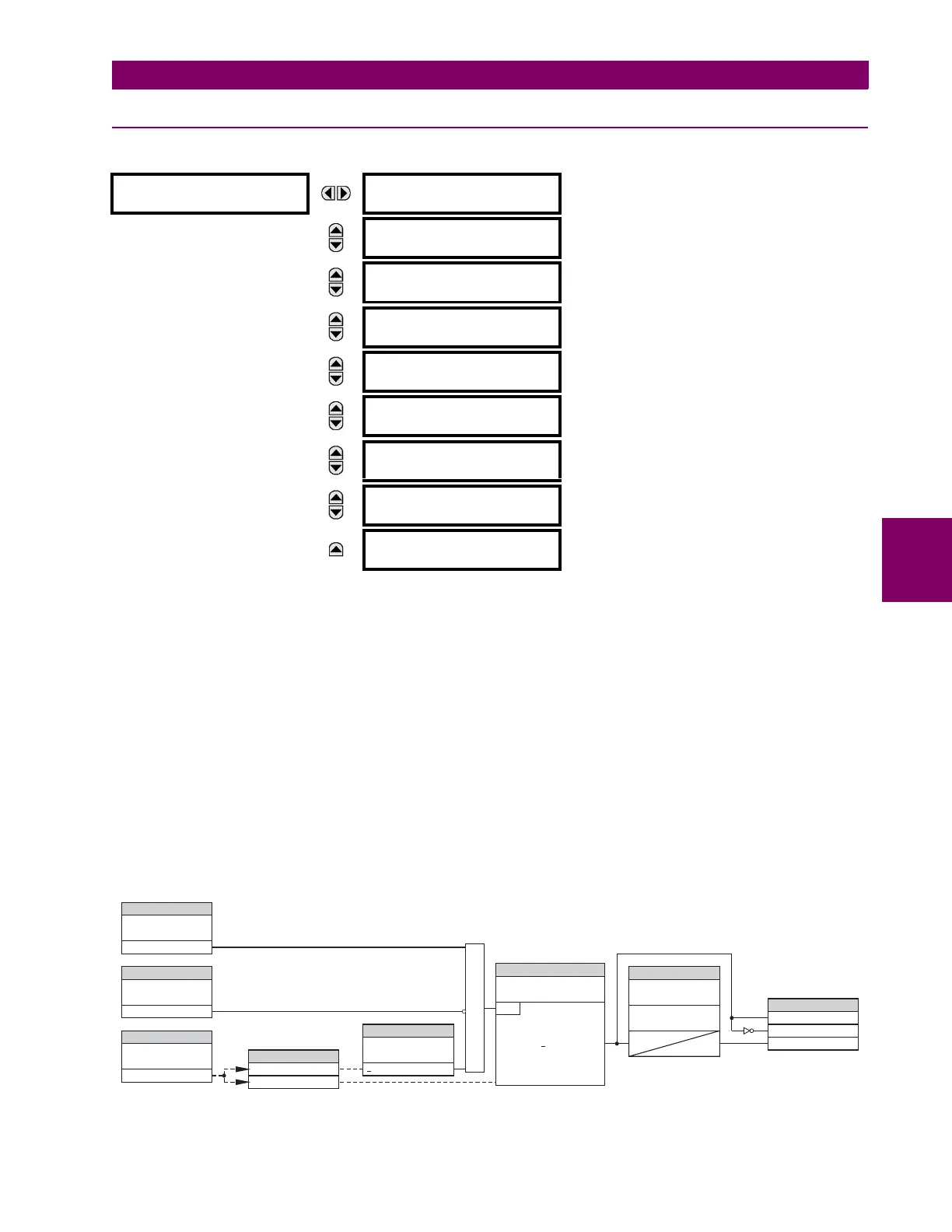
Figure 5–95: UNDERFREQUENCY SCHEME LOGIC
UNDERFREQUENCY 1
UNDFREQ 1 FUNCTION:
Disabled
Range: Disabled, Enabled
MESSAGE
UNDERFREQ 1 BLOCK:
Off
Range: FlexLogic operand
MESSAGE
UNDERFREQ 1 SOURCE:
SRC 1
Range: SRC 1, SRC 2
MESSAGE
UNDERFREQ 1 MIN
VOLT/AMP: 0.10 pu
Range: 0.10 to 1.25 pu in steps of 0.01
MESSAGE
UNDERFREQ 1 PICKUP:
59.50 Hz
Range: 20.00 to 65.00 Hz in steps of 0.01
MESSAGE
UNDERFREQ 1 PICKUP
DELAY: 2.000 s
Range: 0.000 to 65.535 s in steps of 0.001
MESSAGE
UNDERFREQ 1 RESET
DELAY : 2.000 s
Range: 0.000 to 65.535 s in steps of 0.001
MESSAGE
UNDERFREQ 1 TARGET:
Self-reset
Range: Self-reset, Latched, Disabled
MESSAGE
UNDERFREQ 1 EVENTS:
Disabled
Range: Disabled, Enabled
827079A9.CDR
FLEXLOGIC OPERANDS
UNDERFREQ 1 FUNCTION:
UNDERFREQ 1 BLOCK:
UNDERFREQ 1 SOURCE:
UNDERFREQ 1
MIN VOLT / AMP:
UNDERFREQ 1
PICKUP :
UNDERFREQ 1 DPO
UNDERFREQ 1 OP
UNDERFREQ 1 PKP
RUN
Min
AND
SETTING
SETTING
UNDERFREQ 1
RESET DELAY :
UNDERFREQ 1
PICKUP DELAY :
SETTING
Enabled=1
ACTUAL VALUES
t
PKP
t
RST
SETTING
SETTING
SETTING
Off = 0
VOLT / AMP
Level
Frequency
0 < f PICKUP
<
<
 Loading...


