GE Multilin L30 Line Current Differential System 3-33
3 HARDWARE 3.3 PILOT CHANNEL COMMUNICATIONS
3
3.3.4 G.703 INTERFACE
a) DESCRIPTION
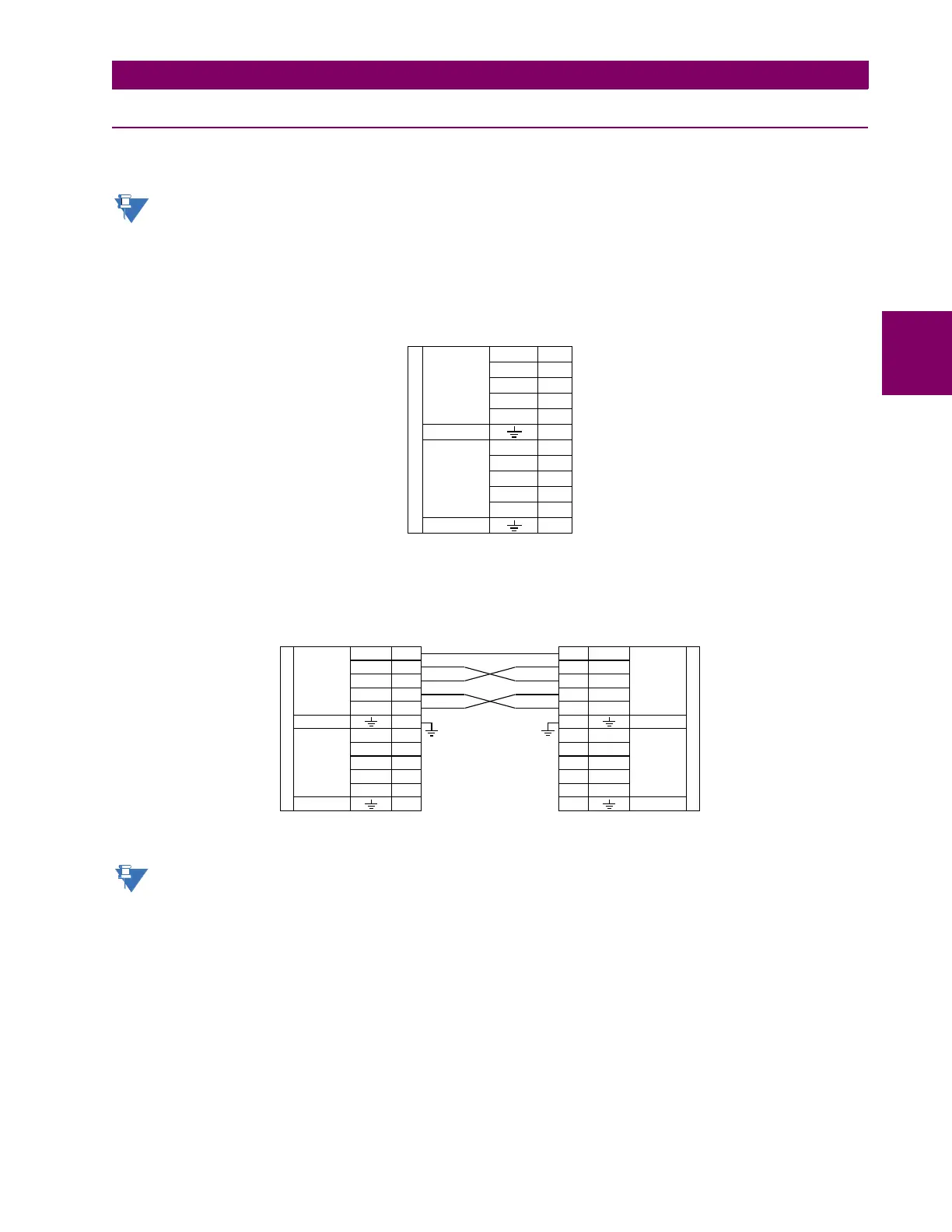
The following figure shows the 64K ITU G.703 co-directional interface configuration.
The G.703 module is fixed at 64 kbps. The SETTINGS > PRODUCT SETUP > DIRECT I/O > DIRECT I/O DATA
RATE setting is not applicable to this module.
AWG 24
twisted shielded pair is recommended for external connections, with the shield grounded only at one end. Con-
necting the shield to pin X1a or X6a grounds the shield since these pins are internally connected to ground. Thus, if pin X1a
or X6a is used to ground the shield at one end, do not ground the shield at the other end. This interface module is protected
by surge suppression devices.
Figure 3–32: G.703 INTERFACE CONFIGURATION
The following figure shows the typical pin interconnection between two G.703 interfaces. For the actual physical arrange-
ment of these pins, see the Rear Terminal Layout section earlier in this chapter. All pin interconnections are to be main-
tained for a connection to a multiplexer.
Figure 3–33: TYPICAL PIN INTERCONNECTION BETWEEN TWO G.703 INTERFACES
Pin nomenclature can differ from one manufacturer to another. Therefore, it is not uncommon to see pinouts num-
bered TxA, TxB, RxA and RxB. In such cases, it can be assumed that “A” is equivalent to “+” and “B” is equivalent
to “–”.
b) G.703 SELECTION SWITCH PROCEDURES
1. With the power to the relay off, remove the G.703 module (7R or 7S) as follows. Record the original location of the
module to help ensure that the same or replacement module is inserted into the correct slot.
2. Simultaneously pull the ejector/inserter clips located at the top and at the bottom of each module in order to release the
module for removal.
3. Remove the module cover screw.
4. Remove the top cover by sliding it towards the rear and then lift it upwards.
5. Set the timing selection switches (channel 1, channel 2) to the desired timing modes.
842773A3.CDR
~8a
~8b
7S
Rx +
Tx +
Shield
Tx –
Shield
Rx –
Tx –
Rx +
Tx +
Rx –
G.703 communications
~2b
~6a
~7a
~1b
~1a
~3a
~6b
~7b
~2a
~3b
G.703
channel 2
G.703
channel 1
Surge
Surge
X8a
X8b
7S
Rx +
Tx +
Shield
Tx –
Shield
Rx –
Tx –
Rx +
Tx +
Rx –
G.703 communications
X2b
X6a
X7a
X1b
X1a
X3a
X6b
X7b
X2a
X3b
G.703
channel 2
G.703
channel 1
Surge
Surge
831727A5.CDR
X8a
X8b
7S
Rx +
Tx +
Shield
Tx –
Shield
Rx –
Tx –
Rx +
Tx +
Rx –
G.703 communications
X2b
X6a
X7a
X1b
X1a
X3a
X6b
X7b
X2a
X3b
G.703
channel 2
G.703
channel 1
Surge
Surge
 Loading...


