GE Multilin L30 Line Current Differential System 5-69
5 SETTINGS 5.2 PRODUCT SETUP
5
The UR device maintains two times: local time and Universal Coordinated Time (UTC). Local time can be provided by IRIG-
B signals. UTC time is provided by SNTP servers.
The real-time clock (RTC) and time stamps reported in historical records and communication protocols can be incorrect if
the Local Time settings are not configured properly.
See the IRIG-B section in the Installation chapter for guidance on these settings when using an IRIG-B source that sets the
IRIG-B control bits according to IEEE Std 1344-1995.
The LOCAL TIME OFFSET FROM UTC setting is used to specify the local time zone offset from UTC (Greenwich Mean Time) in
hours. Time zones in the eastern hemisphere have positive values; time zones in the western hemisphere have negative
values. A value of zero causes the relay to use UTC for local time. This setting has two uses. When the system RTC is syn-
chronized with a communications protocol providing only local time or it is free-running, the offset setting is used to calcu-
late UTC from the local time these provide. When the RTC is synchronized with a communications protocol providing only
UTC (such as PTP or SNTP), the time offset setting is used to determine local time from the UTC provided. PTP
ALTERNATE_TIME_OFFSET_INDICATOR TLVs are not used to calculate local time.
The
DAYLIGHT SAVINGS TIME (DST) settings can be used to allow the relay to follow the DST rules of the local time zone.
Note that when IRIG-B time synchronization is active, the local time in the IRIG-B signal contains any daylight savings time
offset and so the DST settings are ignored.
5.2.7 FAULT REPORTS
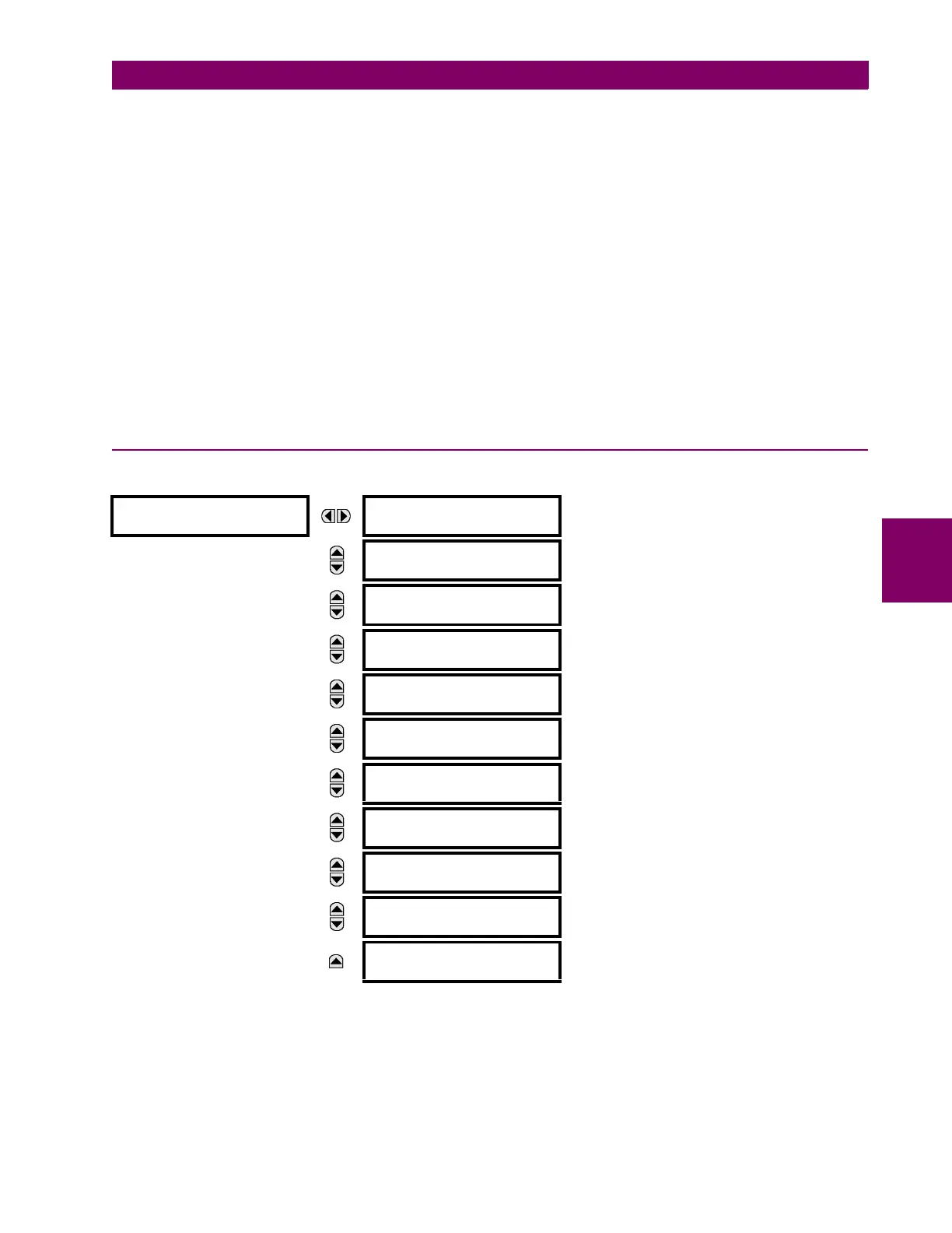
PATH: SETTINGS PRODUCT SETUP FAULT REPORTS FAULT REPORT 1
The L30 relay supports one fault report and an associated fault locator. The signal source and trigger condition, as well as
the characteristics of the line or feeder, are entered in this menu.
The fault report stores data, in non-volatile memory, pertinent to an event when triggered. The captured data contained in
the FaultReport.txt file includes:
• Fault report number.
• Name of the relay, programmed by the user.
FAULT REPORT 1
FAULT REPORT 1
SOURCE: SRC 1
Range: SRC 1, SRC 2
MESSAGE
FAULT REPORT 1 TRIG:
Off
Range: FlexLogic operand
MESSAGE
FAULT REPORT 1 Z1
MAG: 3.00 Ω
Range: 0.01 to 250.00 ohms in steps of 0.01
MESSAGE
FAULT REPORT 1 Z1
ANGLE: 75°
Range: 25 to 90° in steps of 1
MESSAGE
FAULT REPORT 1 Z0
MAG: 9.00 Ω
Range: 0.01 to 650.00 ohms in steps of 0.01
MESSAGE
FAULT REPORT 1 Z0
ANGLE: 75°
Range: 25 to 90° in steps of 1
MESSAGE
FAULT REPORT 1 LINE
LENGTH UNITS: km
Range: km, miles
MESSAGE
FAULT REP 1 LENGTH
(km ): 100.0
Range: 0.0 to 2000.0 in steps of 0.1
MESSAGE
FAULT REPORT 1 VT
SUBSTITUTION: None
Range: None, I0, V0
MESSAGE
FAULT REP 1 SYSTEM
Z0 MAG: 2.00 Ω
Range: 0.01 to 650.00 ohms in steps of 0.01
MESSAGE
FAULT REP 1 SYSTEM
Z0 ANGLE: 75°
Range: 25 to 90° in steps of 1
 Loading...


