GE Multilin L30 Line Current Differential System 3-11
3 HARDWARE 3.2 WIRING
3
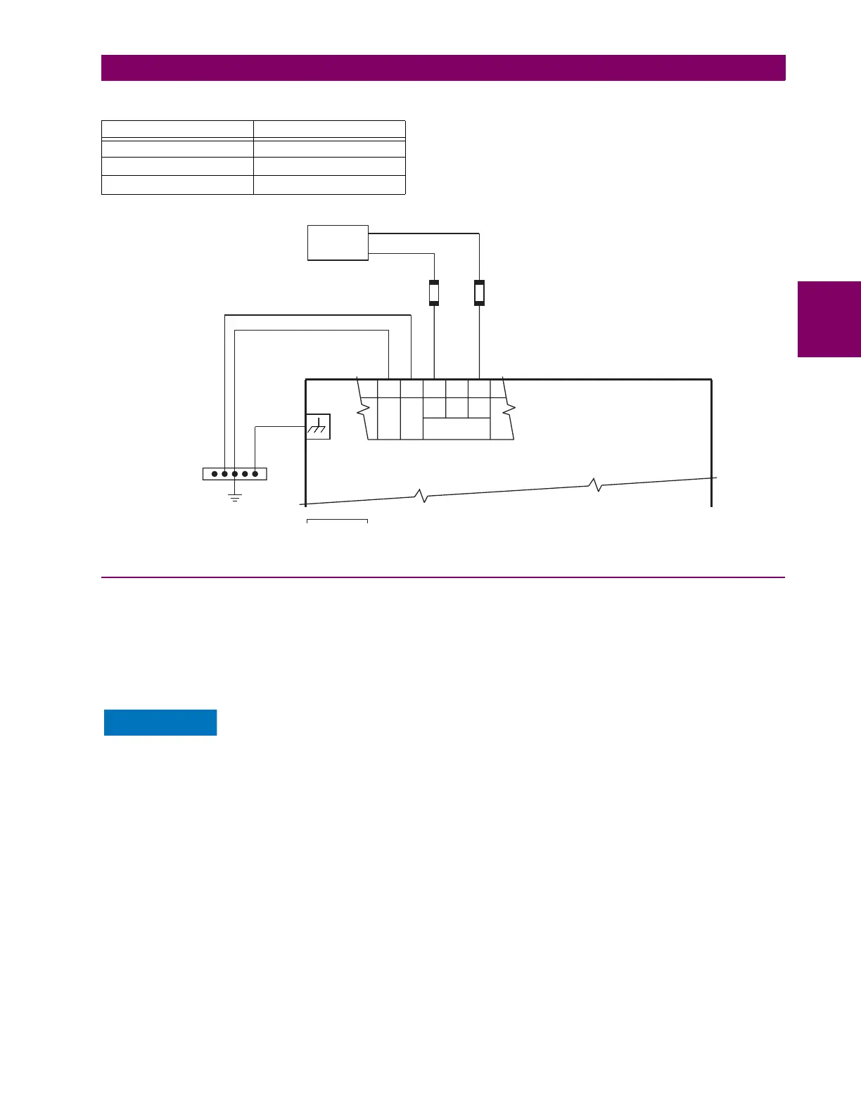
An LED on the front of the control power module shows the status of the power supply:
Figure 3–11: CONTROL POWER CONNECTION
3.2.4 CT AND VT MODULES
A CT/VT module can have voltage or current inputs on channels 1 through 4 inclusive, or channels 5 through 8 inclusive.
Channels 1 and 5 are intended for connection to phase A, and are labeled as such in the relay. Likewise, channels 2 and 6
are intended for connection to phase B, and channels 3 and 7 are intended for connection to phase C.
Channels 4 and 8 are intended for connection to a single-phase source. For voltage inputs, these channel are labelled as
auxiliary voltage (VX). For current inputs, these channels are intended for connection to a CT between system neutral and
ground, and are labelled as ground current (IG).
Verify that the connection made to the relay terminals for nominal current of 1 A or 5 A matches the
secondary rating of the connected CTs. Unmatched CTs can result in equipment damage or inade-
quate protection.
To connect the module, size 12 American Wire Gauge (AWG) is commonly used; the maximum size is 10 AWG.
CT/VT modules can be ordered with a standard ground current input that is the same as the phase current input. Each AC
current input has an isolating transformer and an automatic shorting mechanism that shorts the input when the module is
withdrawn from the chassis. There are no internal ground connections on the current inputs. Current transformers with 1 to
50000 A primaries and 1 A or 5 A secondaries can be used.
The above modules have enhanced diagnostics that can automatically detect CT/VT hardware failure and take the relay
out of service.
CT connections for both ABC and ACB phase rotations are identical as shown in the Typical wiring diagram.
The exact placement of a zero-sequence core balance CT to detect ground fault current is shown as follows. Twisted-pair
cabling on the zero-sequence CT is recommended.
LED INDICATION POWER SUPPLY
CONTINUOUS ON OK
ON / OFF CYCLING Failure
OFF Failure
AC or DC
NOTE:
14 gauge stranded
wire with suitable
disconnect devices
is recommended.
Heavy copper conductor
or braided wire
Switchgear
ground bus
UR-series
protection system
FILTER
SURGE
–
+
LOW
+
HIGH
B8b B8a B6a B6b B5b
CONTROL
POWER
827247A1.CDR
 Loading...


