GE Multilin L30 Line Current Differential System 4-13
4 HUMAN INTERFACES 4.3 FACEPLATE INTERFACE
4
4.3FACEPLATE INTERFACE 4.3.1 FACEPLATE
a) ENHANCED FACEPLATE
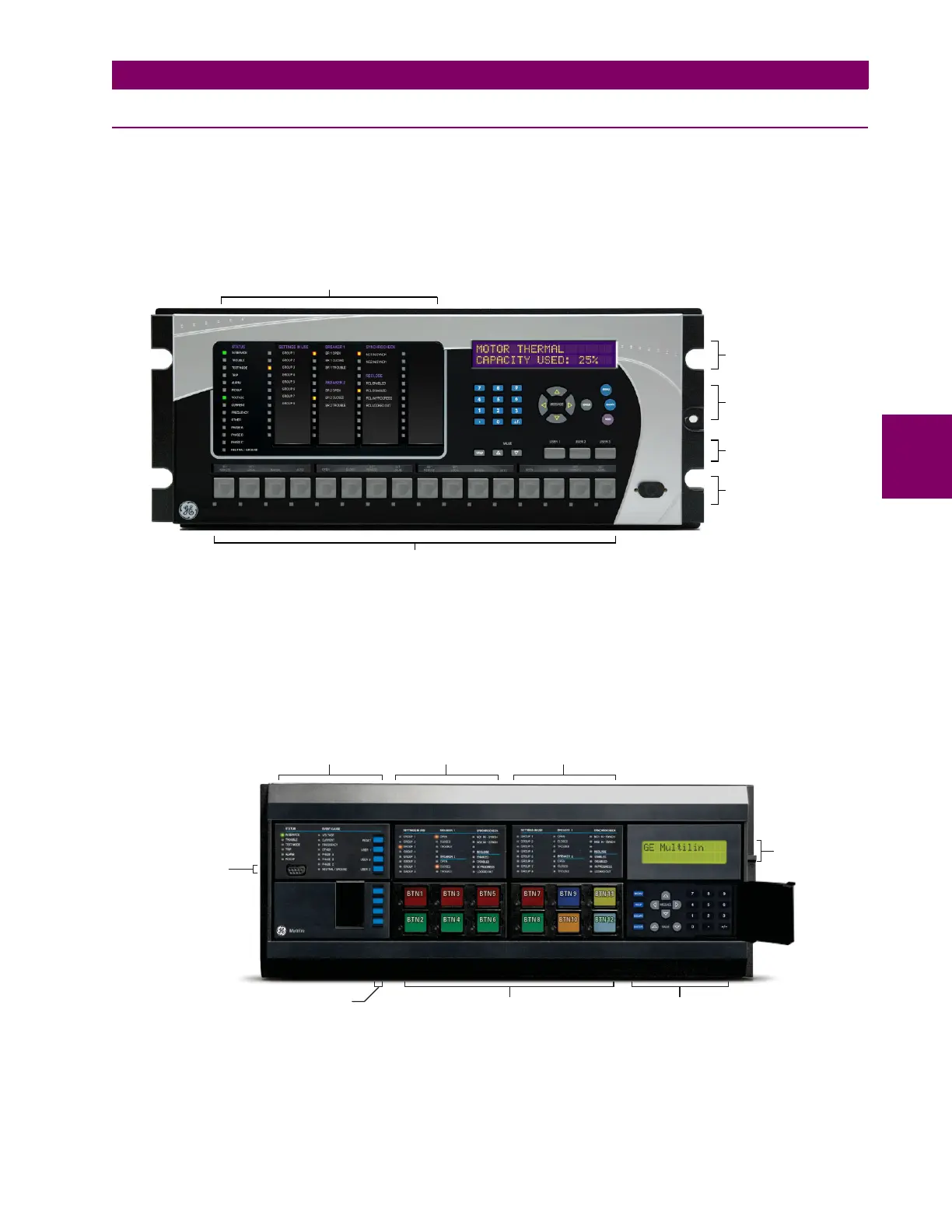
The front panel interface is one of two supported interfaces, the other interface being EnerVista UR Setup software. The
front panel interface consists of LED panels, an RS232 port, keypad, LCD display, control pushbuttons, and optional user-
programmable pushbuttons.
The faceplate is hinged to allow easy access to the removable modules.
Figure 4–15: UR-SERIES ENHANCED FACEPLATE
b) STANDARD FACEPLATE
There are two interfaces: the front panel and the EnerVista UR Setup software. The front panel interface consists of LED
panels, an RS232 port, keypad, LCD display, control pushbuttons, and optional user-programmable pushbuttons.
The faceplate is hinged to allow easy access to the removable modules. There is also a removable dust cover that fits over
the faceplate that must be removed in order to access the keypad panel. The following figure shows the horizontal arrange-
ment of the faceplate panels.
Figure 4–16: UR-SERIES STANDARD HORIZONTAL FACEPLATE PANELS
Five column LED indicator panel
Display
User-programmable pushbuttons 1 to 16
842810A2.CDR
Keypad
Front panel
RS232 port
Control
pushbuttons (3)
LED panel 1
LED panel 2
Display
User-programmable
pushbuttons 1 to 12
Keypad
Front panel
RS232 port
Small user-programmable
(control) pushbuttons 1 to 7
LED panel 3
827801A9.CDR
 Loading...


