GE Multilin L30 Line Current Differential System 5-257
5 SETTINGS 5.8 INPUTS AND OUTPUTS
5
When using GOOSE Analogs and PU base in FlexElements, the largest value that can be displayed in the FlexEle-
ment actual values is 2,140,000.000.
The GOOSE analog input FlexAnalog values are available for use in other L30 functions that use FlexAnalog values.
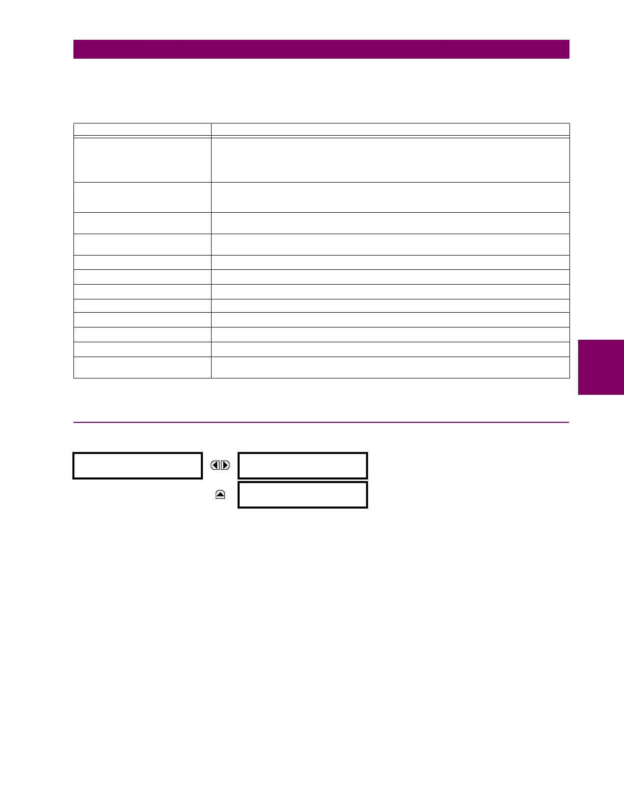
5.8.12 IEC 61850 GOOSE INTEGERS
PATH: SETTINGS INPUTS/OUTPUTS IEC 61850 GOOSE UINTEGERS GOOSE UINTEGER INPUT 1(16)
The IEC 61850 GOOSE uinteger inputs feature allows the transmission of FlexInteger values between any two UR-series
devices. The following settings are available for each GOOSE uinteger input.
• UINTEGER 1 DEFAULT: This setting specifies the value of the GOOSE uinteger input when the sending device is
offline and the UINTEGER 1 DEFAULT MODE is set to “Default Value”.This setting is stored as a 32-bit unsigned integer
number.
• UINTEGER 1 DEFAULT MODE: When the sending device is offline and this setting is “Last Known”, the value of the
GOOSE uinteger input remains at the last received value. When the sending device is offline and this setting value is
“Default Value”, then the value of the GOOSE uinteger input is defined by the
UINTEGER 1 DEFAULT setting.
The GOOSE integer input FlexInteger values are available for use in other L30 functions that use FlexInteger values.
Table 5–34: GOOSE ANALOG INPUT BASE UNITS
ELEMENT BASE UNITS
87L SIGNALS
(Local IA Mag, IB, and IC)
(Diff Curr IA Mag, IB, and IC)
(Terminal 1 IA Mag, IB, and IC)
(Terminal 2 IA Mag, IB and IC)
I
BASE
= maximum primary RMS value of the +IN and –IN inputs
(CT primary for source currents, and 87L source primary current for line differential currents)
87L SIGNALS
(Op Square Curr IA, IB, and IC)
(Rest Square Curr IA, IB, and IC)
BASE = Squared CT secondary of the 87L source
BREAKER ARCING AMPS
(Brk X Arc Amp A, B, and C)
BASE = 2000 kA
2
× cycle
dcmA BASE = maximum value of the
DCMA INPUT MAX setting for the two transducers configured
under the +IN and –IN inputs.
FREQUENCY f
BASE
= 1 Hz
PHASE ANGLE ϕ
BASE
= 360 degrees (see the UR angle referencing convention)
POWER FACTOR PF
BASE
= 1.00
RTDs BASE = 100°C
SOURCE CURRENT I
BASE
= maximum nominal primary RMS value of the +IN and –IN inputs
SOURCE POWER P
BASE
= maximum value of V
BASE
× I
BASE
for the +IN and –IN inputs
SOURCE VOLTAGE V
BASE
= maximum nominal primary RMS value of the +IN and –IN inputs
SYNCHROCHECK
(Max Delta Volts)
V
BASE
= maximum primary RMS value of all the sources related to the +IN and –IN inputs
GOOSE UINTEGER
INPUT 1
UINTEGER 1 DEFAULT:
1000
Range: 0 to 429496295 in steps of 1
MESSAGE
UINTEGER 1 DEFAULT
MODE: Default Value
Range: Default Value, Last Known
 Loading...


