GE Multilin L30 Line Current Differential System 3-39
3 HARDWARE 3.3 PILOT CHANNEL COMMUNICATIONS
3
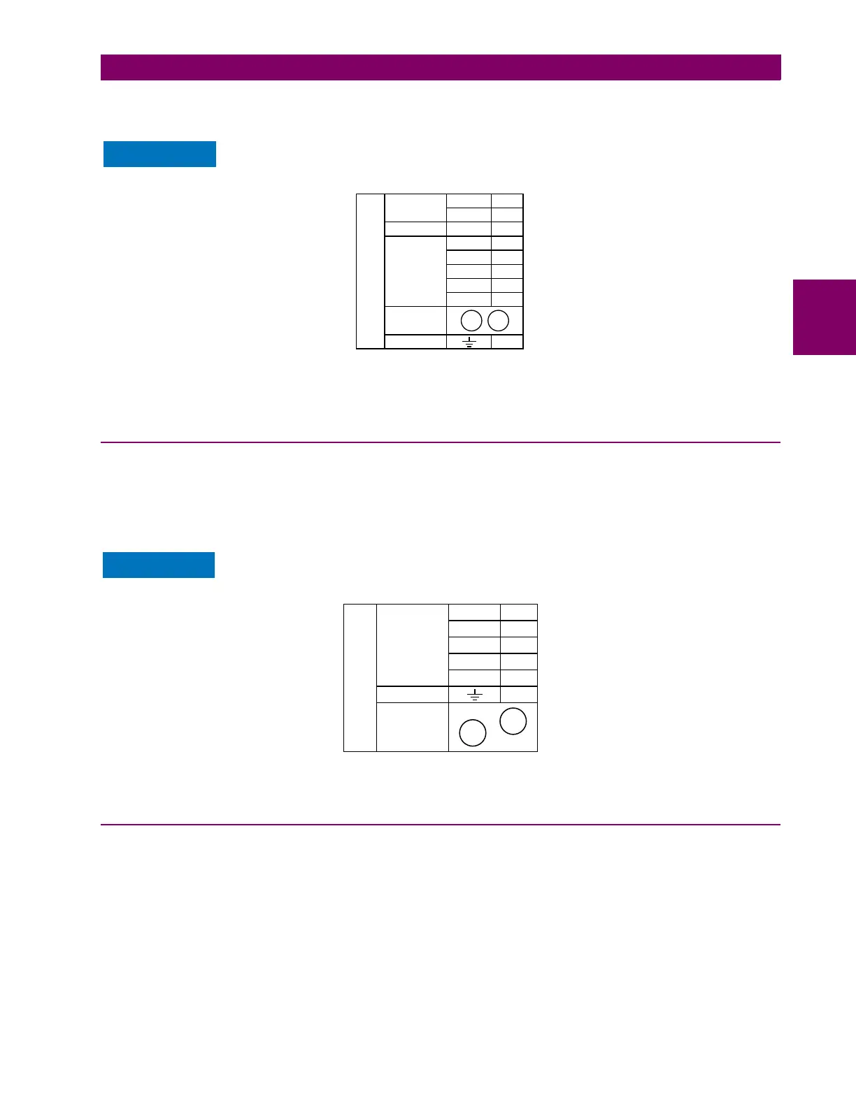
AWG 20-24 twisted shielded pair is recommended for external RS422 connections and ground the shield only at one end.
For the direct fiber channel, address power budget issues properly.
When using a LASER Interface, attenuators can be necessary to ensure that you do not exceed
maximum optical input power to the receiver.
Figure 3–42: RS422 AND FIBER INTERFACE CONNECTION
Connections shown above are for multiplexers configured as DCE (data communications equipment) units.
3.3.8 G.703 AND FIBER INTERFACE
The figure below shows the combined G.703 plus fiberoptic interface configuration at 64 kbps. The 7E, 7F, 7G, 7Q, and 75
modules are used in configurations where channel 1 is employed via the G.703 interface (possibly with a multiplexer) and
channel 2 via direct fiber. AWG 24 twisted shielded pair is recommended for external G.703 connections connecting the
shield to pin 1a at one end only. For the direct fiber channel, address power budget issues properly. See previous sections
for additional details on the G.703 and fiber interfaces.
When using a laser Interface, attenuators can be necessary to ensure that you do not exceed the
maximum optical input power to the receiver.
Figure 3–43: G.703 AND FIBER INTERFACE CONNECTION
3.3.9 IEEE C37.94 INTERFACE
The UR-series IEEE C37.94 communication modules (modules types 2I, 2J, 76, and 77) are designed to interface with
IEEE C37.94 compliant digital multiplexers or an IEEE C37.94 compliant interface converter for use with direct input and
output applications. The IEEE C37.94 standard defines a point-to-point optical link for synchronous data between a multi-
plexer and a teleprotection device. This data is typically 64 kbps, but the standard provides for speeds up to 64n kbps,
where n = 1, 2,…, 12. The UR-series C37.94 communication modules are either 64 kbps (with n fixed at 1) or 128 kbps
(with n fixed at 2). The frame is a valid International Telecommunications Union (ITU-T) recommended G.704 pattern from
the standpoint of framing and data rate. The frame is 256 bits and is repeated at a frame rate of 8000 Hz, with a resultant bit
rate of 2048 kbps.
The specifications for the module are as follows:.
Tx2
Rx2
842777A3.CDR
~8a
7L, 7M, 7N,
7P, and 74
Shield
Tx –
Rx –
Tx +
Rx +
RS422
communications
~4b
~3a
~3b
~6a
~2a
RS422
channel 1
Surge
+
–
~1a
~1b
Clock
channel 1
Common
~2b
COM
Fiber
channel 2
Rx2
Tx2
842778A2.CDR
~3b
75, 7E, 7F, 7G,
and 7Q
Rx +
Shield
Tx –
Rx –
Tx +
G.703
communications
~2b
~1b
~1a
~3a
~2a
G.703
channel 1
Surge
Fiber
channel 2
 Loading...


