GE Multilin L30 Line Current Differential System 11-1
11 MAINTENANCE 11.1 MODULES
11
11 MAINTENANCE 11.1 MODULES 11.1.1 REPLACE A MODULE
Withdraw or insert a module only when control power has been removed from the unit, and
be sure to insert only the correct module type into a slot, else personal injury, damage to the
unit or connected equipment, or undesired operation can result.
To avoid damage to the equipment, use proper electrostatic discharge protection (for example, a
static strap) when coming in contact with modules while the relay is energized.
The relay, being modular in design, allows for the withdrawal and insertion of modules. Modules must only be replaced with
like modules in their original factory configured slots.
The enhanced faceplate can be opened to the left, once the thumb screw has been removed, as shown below. This allows
for easy accessibility of the modules for withdrawal. The new wide-angle hinge assembly in the enhanced front panel opens
completely and allows easy access to all modules in the L30.
Figure 11–1: UR MODULE WITHDRAWAL AND INSERTION (ENHANCED FACEPLATE)
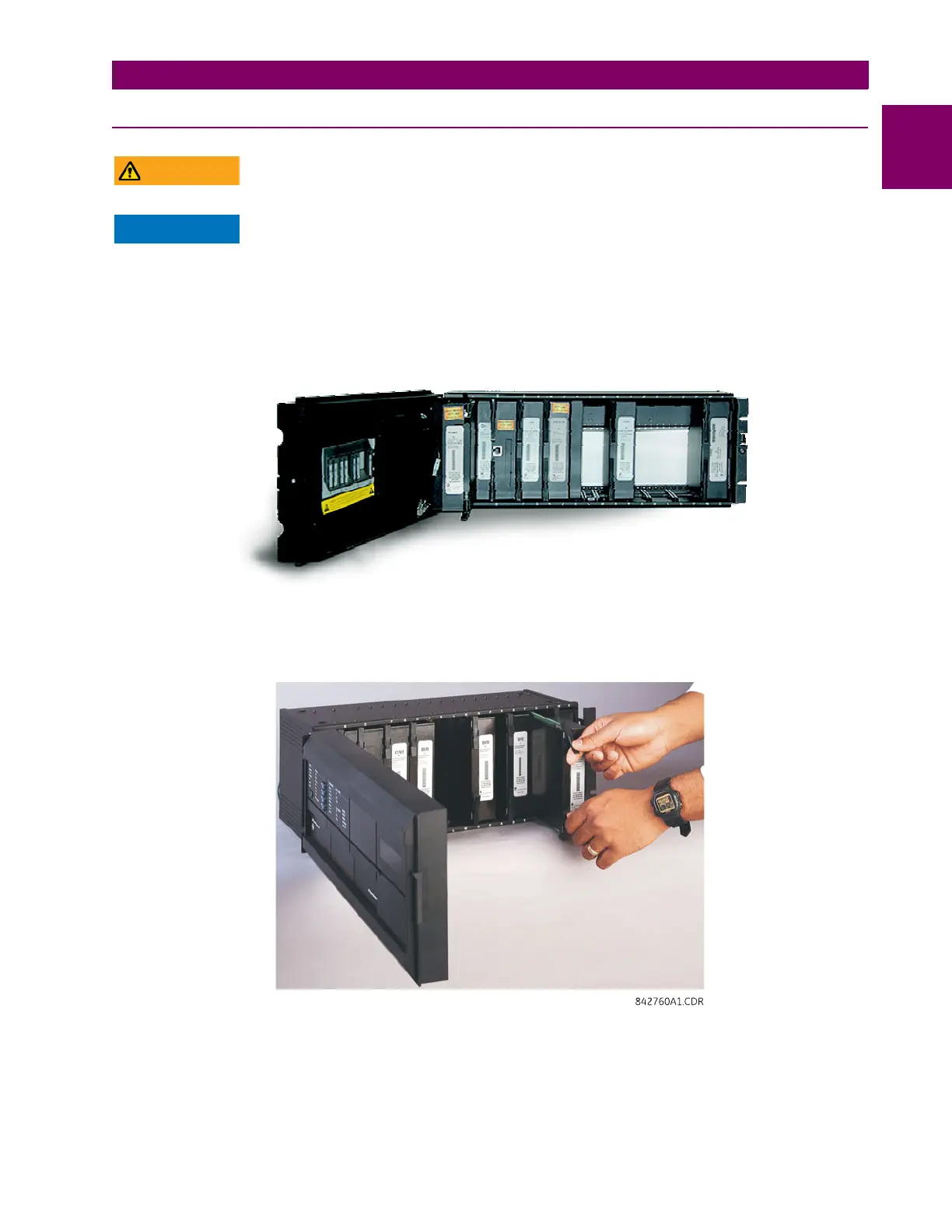
The standard faceplate can be opened to the left, once the sliding latch on the right side has been pushed up, as shown
below. This allows for easy accessibility of the modules for withdrawal.
Figure 11–2: UR MODULE WITHDRAWAL AND INSERTION (STANDARD FACEPLATE)
 Loading...


