5-256 L30 Line Current Differential System GE Multilin
5.8 INPUTS AND OUTPUTS 5 SETTINGS
5
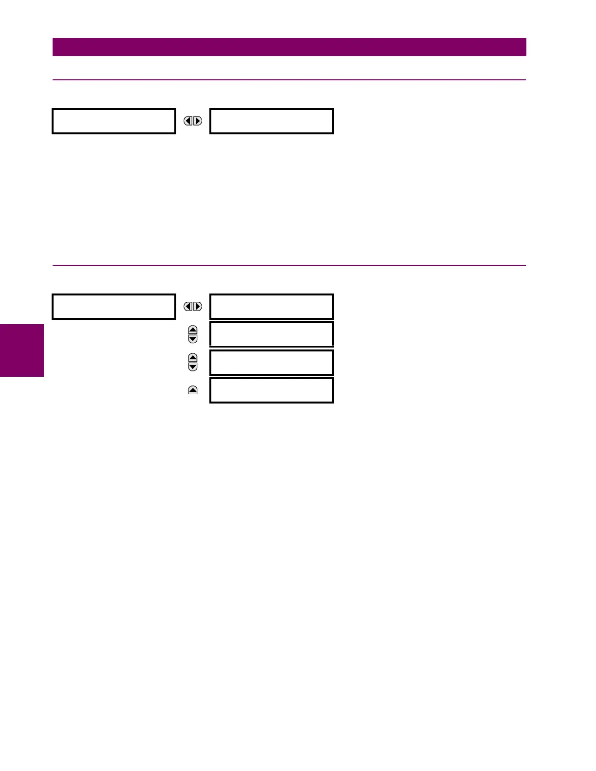
5.8.10 RESETTING
PATH: SETTINGS INPUTS/OUTPUTS RESETTING
Some events can be programmed to latch the faceplate LED event indicators, target message, and/or graphical panel
annunciator windows. Once set, the latching mechanism holds all of the latched indicators or messages in the set state
after the initiating condition has cleared until a RESET command is received to return these latches (not including FlexLogic
latches) to the reset state where the initiating condition has cleared. The RESET command can be sent from the faceplate
Reset button, a remote device via a communications channel, or any selected operand.
The three sources of RESET commands each activates the
RESET OP FlexLogic operand. Each individual source of a
RESET command also creates its individual operand RESET OP (PUSHBUTTON), RESET OP (COMMS), or RESET OP (OPER-
AND)
to identify the source of the command. Each of these three operands generates an event in the event record when
activated. The setting shown above selects the operand that activates the RESET OP (OPERAND) operand.
5.8.11 IEC 61850 GOOSE ANALOGS
PATH: SETTINGS INPUTS/OUTPUTS IEC 61850 GOOSE ANALOGS GOOSE ANALOG INPUT 1(32)
The IEC 61850 GOOSE analog inputs feature allows the transmission of analog values between any two UR-series
devices. The following settings are available for each GOOSE analog input.
• ANALOG 1 DEFAULT: This setting specifies the value of the GOOSE analog input when the sending device is offline
and the ANALOG 1 DEFAULT MODE is set to “Default Value”.This setting is stored as an IEEE 754 / IEC 60559 floating
point number. Because of the large range of this setting, not all possible values can be stored. Some values may be
rounded to the closest possible floating point number.
• ANALOG 1 DEFAULT MODE: When the sending device is offline and this setting is “Last Known”, the value of the
GOOSE analog input remains at the last received value. When the sending device is offline and this setting value is
“Default Value”, then the value of the GOOSE analog input is defined by the
ANALOG 1 DEFAULT setting.
• GOOSE ANALOG 1 UNITS: This setting specifies a four-character alphanumeric string that can is used in the actual
values display of the corresponding GOOSE analog input value.
GOOSE Analogs are floating-point values, with no units. The GOOSE UNIT and PU base settings allow the user to
configure GOOSE Analog, so that it can be used in a FlexElement.
GOOSE Analogs that represent current, voltage, power, frequency, angles, or power factor can be used in a FlexEle-
ment. The following text must be used in the UNITS setting, to represent these types of analogs: A, V, W, var, VA, Hz,
deg, and no text (blank setting) for power factor.
GOOSE Analogs can be compared to other GOOSE Analogs with any character string or no string.
• GOOSE ANALOG 1 PU: This setting specifies the per-unit base factor when using the GOOSE analog input FlexAna-
log values in other L30 features, such as FlexElements. The base factor is applied to the GOOSE analog input FlexAn-
alog quantity to normalize it to a per-unit quantity. The base units are described in the following table.
The per-unit base setting represents thousands, not single units. For example, a PU base of 1.000 is actually 1000 and
a PU base of 0.001 is 1.
RESETTING
RESET OPERAND:
Off
Range: FlexLogic operand
GOOSE ANALOG
INPUT 1
ANALOG 1 DEFAULT:
1000.000
Range: –1000000.000 to 1000000.000 in steps of 0.001
MESSAGE
ANALOG 1 DEFAULT
MODE: Default Value
Range: Default Value, Last Known
MESSAGE
GOOSE ANALOG 1
UNITS:
Range: up to 4 alphanumeric characters
MESSAGE
GOOSE ANALOG 1 PU:
1.000
Range: 0.000 to 1000000000.000 in steps of 0.001
 Loading...


