8-10 L30 Line Current Differential System GE Multilin
8.1 OVERVIEW 8 THEORY OF OPERATION
8
8.1.12 PHASE LOCKING FILTER
Filters are used in the phase locked loop to assure stability, to reduce phase and frequency noise. This is well known tech-
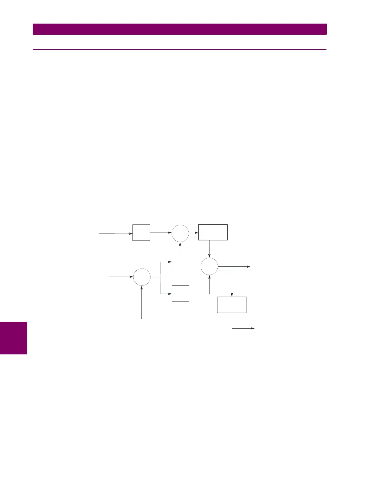
nology. The primary feedback mechanism shown in the Loop Block Diagram is phase angle information through the well
known proportional plus integral (PI) filter (the Z in the diagram refers to a unit delay, and 1 / (Z – 1) represents a simple
digital first order integrator). This loop is used to provide stability and zero steady state error.
A PI filter has two time parameters that determine dynamic behavior: the gain for the proportional term and the gain for the
integral. Depending on the gains, the transient behavior of the loop can be underdamped, critically damped, or over
damped. For this application, critically damped is a good choice.
This sets a constraint relating the two parameters. A second constraint is derived from the desired time constants of the
loop. By considering the effects of both phase and frequency noise in this application it can be shown that optimum behav-
ior results with a certain proportion between phase and frequency constraints.
A secondary input is formed through the frequency deviation input of the filter. Whenever frequency deviation information is
available, it is used for this input; otherwise, the input is zero. Because frequency is the derivative of phase information, the
appropriate filter for frequency deviation is an integrator, which is combined with the integrator of the PI filter for the phase.
It is very important to combine these two integrators into a single function because it can be shown if two separate integra-
tors are used, they can drift in opposite directions into saturation, because the loop would only drive their sum to zero.
In normal operation, frequency tracking at each terminal matches the tracking at all other terminals, because all terminals
will measure approximately the same frequency deviation. However, if there is not enough current at a terminal to compute
frequency deviation, frequency tracking at that terminal is accomplished indirectly via phase locking to other terminals. A
small phase deviation must be present for the tracking to occur.
Also shown in the loop is the clock itself, because it behaves like an integrator. The clock is implemented in hardware and
software with a crystal oscillator and a counter.
Figure 8–3: BLOCK DIAGRAM OF LOOP FILTER
There are 4 gains in the filter that must be selected once and for all as part of the design of the system. The gains are deter-
mined by the time step of the integrators, and the desired time constants of the system as follows:
(EQ 8.27)
where: T
repeat
= the time between execution of the filter algorithm
T
phase
= time constant for the primary phase locked loop
T
frequency
= time constant for the frequency locked loop
831028A1.CDR
+
+
+
+
+
Delta frequency
Delta phi time
KI
KF
1/(Z–1)
New frequency
1/(Z–1)
Clock
(sample timer)
phi
KP
GPS channel
asymmetry
+
–
+
+
KI
T
repeat
T
phase
2
------------------
= , KP
2
T
phase
-----------------
= , KF
T
repeat
T
frequency
--------------------------
=
 Loading...


