GE Multilin L30 Line Current Differential System 3-31
3 HARDWARE 3.3 PILOT CHANNEL COMMUNICATIONS
3
3.3PILOT CHANNEL COMMUNICATIONS 3.3.1 DESCRIPTION
A special inter-relay communications module is available for the L30. This module is plugged into slot “W” in horizontally
mounted units and slot “R” in vertically mounted units. Inter-relay channel communications is not the same as 10/100Base-
F interface communications (available as an option with the CPU module). Channel communication is used for sharing data
among relays.
The inter-relay communications modules are available with several interfaces and some are outlined here in more detail.
Those that apply depend on options purchased. The options are outlined in the Inter-Relay Communications section of the
Order Code tables in Chapter 2.
All of the fiber modules use ST type connectors. For two-terminal applications, each L30 relay requires at least one com-
munications channel.
The current differential function must be “Enabled” for the communications module to properly operate. Refer to
SETTINGS GROUPED ELEMENTS LINE DIFFERENTIAL CURRENT DIFFERENTIAL menu.
The fiber optic modules (7A to 7W) are designed for back-to-back connections of UR-series relays only. For con-
nections to higher-order systems, use the 72 to 77 modules or the 2A and 2B modules.
Observing any fiber transmitter output can injure the eye.
3.3.2 FIBER: LED AND ELED TRANSMITTERS
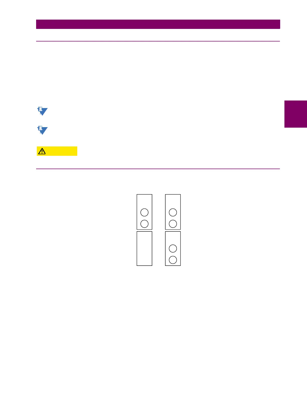
The following figure shows the configuration for the 7A, 7B, 7C, 7H, 7I, and 7J fiber-only modules.
Figure 3–29: LED AND ELED FIBER MODULES
7A, 7B, and
7C modules
7H, 7I, and
7J modules
1 channel 2 channels
Rx1
Rx1
Rx2
Tx1 Tx1
Tx2
831719A3.CDR
 Loading...


