5-252 L30 Line Current Differential System GE Multilin
5.8 INPUTS AND OUTPUTS 5 SETTINGS
5
5.8.6 REMOTE INPUTS
PATH: SETTINGS INPUTS/OUTPUTS REMOTE INPUTS REMOTE INPUT 1(32)
Remote Inputs that create FlexLogic operands at the receiving relay are extracted from GSSE/GOOSE messages originat-
ing in remote devices. Each remote input can be selected from a list consisting of: DNA-1 through DNA-32, UserSt-1
through UserSt-32, and Dataset Item 1 through Dataset Item 32. The function of DNA inputs is defined in the IEC 61850
specification and is presented in the IEC 61850 DNA Assignments table in the Remote Outputs section. The function of
UserSt inputs is defined by the user selection of the FlexLogic operand whose state is represented in the GSSE/GOOSE
message. A user must program a DNA point from the appropriate FlexLogic operand.
Remote input 1 must be programmed to replicate the logic state of a specific signal from a specific remote device for local
use. This programming is performed via the three settings shown above.
The
REMOTE INPUT 1 ID setting allows the user to assign descriptive text to the remote input. The REMOTE IN 1 DEVICE setting
selects the remote device which originates the required signal, as previously assigned to the remote device via the setting
REMOTE DEVICE (16) ID (see the Remote Devices section). The REMOTE IN 1 ITEM setting selects the specific bits of the
GSSE/GOOSE message required.
The REMOTE IN 1 DEFAULT STATE setting selects the logic state for this point if the local relay has just completed startup or
the remote device sending the point is declared to be non-communicating. The following choices are available:
• Setting REMOTE IN 1 DEFAULT STATE to “On” value defaults the input to logic 1.
• Setting REMOTE IN 1 DEFAULT STATE to “Off” value defaults the input to logic 0.
• Setting
REMOTE IN 1 DEFAULT STATE to “Latest/On” freezes the input in case of lost communications. If the latest state is
not known, such as after relay power-up but before the first communication exchange, the input will default to logic 1.
When communication resumes, the input becomes fully operational.
• Setting
REMOTE IN 1 DEFAULT STATE to “Latest/Off” freezes the input in case of lost communications. If the latest state is
not known, such as after relay power-up but before the first communication exchange, the input will default to logic 0.
When communication resumes, the input becomes fully operational.
For additional information on GSSE/GOOOSE messaging, see the Remote Devices section in this chapter.
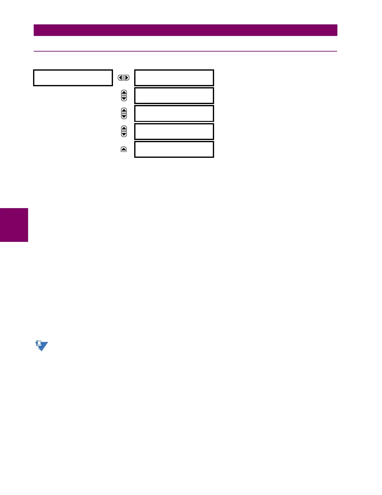
REMOTE INPUT 1
REMOTE INPUT 1 ID:
Remote Ip 1
Range: up to 12 alphanumeric characters
MESSAGE
REMOTE IN 1 DEVICE:
Remote Device 1
Range: Remote Device 1 to Remote device 16
MESSAGE
REMOTE IN 1 ITEM:
None
Range: None, DNA-1 to DNA-32, UserSt-1 to UserSt-32,
Config Item 1 to Config Item 32
MESSAGE
REMOTE IN 1 DEFAULT
STATE: Off
Range: On, Off, Latest/On, Latest/Off
MESSAGE
REMOTE IN 1
EVENTS: Disabled
Range: Disabled, Enabled
 Loading...


