GE Multilin L30 Line Current Differential System 5-261
5 SETTINGS 5.9 TRANSDUCER INPUTS AND OUTPUTS
5
5.9.3 DCMA OUTPUTS
PATH: SETTINGS TRANSDUCER I/O DCMA OUTPUTS DCMA OUTPUT H1(U8)
Hardware and software is provided to generate DCmA signals that allow interfacing with external equipment. Specific hard-
ware details are contained in chapter 3. The DCmA output channels are arranged in a manner similar to transducer input or
CT and VT channels. The user configures individual channels with the settings shown below.
The channels are arranged in sub-modules of two channels, numbered 1 through 8 from top to bottom. On power-up, the
relay automatically generates configuration settings for every channel, based on the order code, in the same manner used
for CTs and VTs. Each channel is assigned a slot letter followed by the row number, 1 through 8 inclusive, which is used as
the channel number.
Both the output range and a signal driving a given output are user-programmable via the following settings menu (an exam-
ple for channel M5 is shown).
The relay checks the driving signal (x in equations below) for the minimum and maximum limits, and subsequently re-
scales so the limits defined as
MIN VAL and MAX VAL match the output range of the hardware defined as RANGE. The follow-
ing equation is applied:
(EQ 5.29)
where: x is a driving signal specified by the SOURCE setting
I
min
and I
max
are defined by the RANGE setting
k is a scaling constant calculated as:
(EQ 5.30)
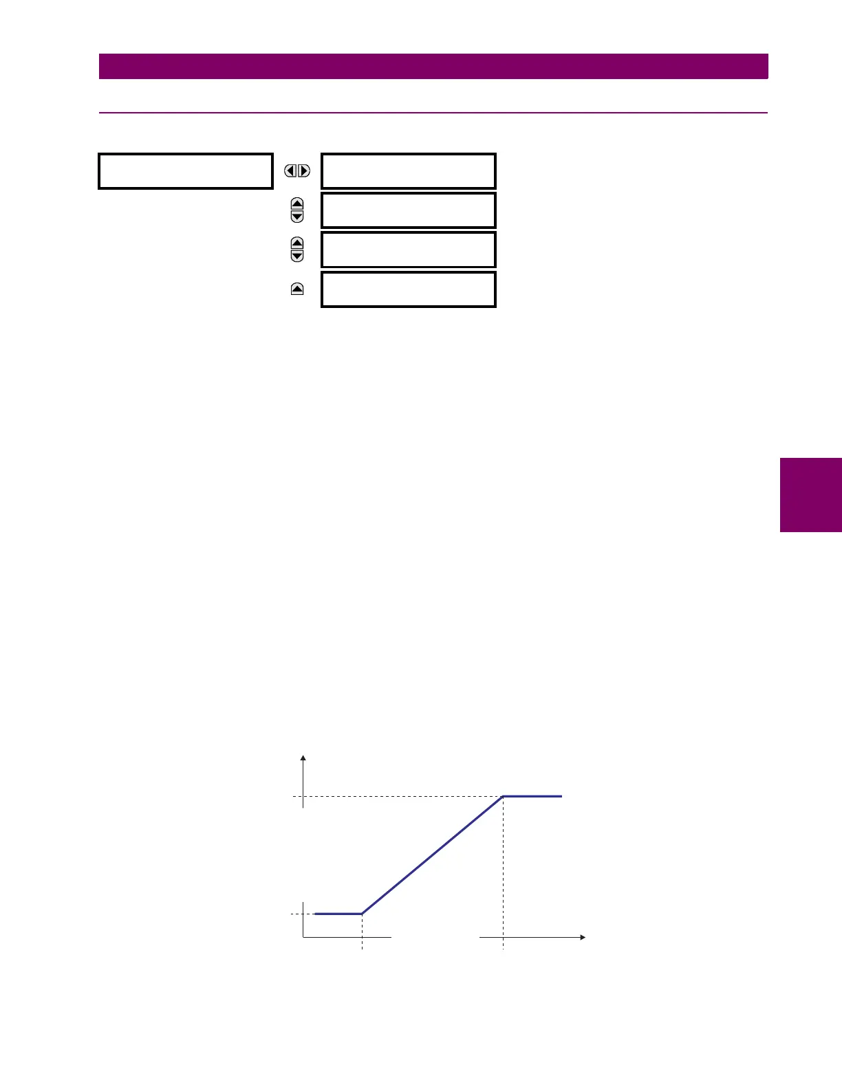
The feature is intentionally inhibited if the MAX VAL and MIN VAL settings are entered incorrectly, e.g. when MAX VAL – MIN
VAL
< 0.1 pu. The resulting characteristic is illustrated in the following figure.
Figure 5–116: DCMA OUTPUT CHARACTERISTIC
DCMA OUTPUT H1
DCMA OUTPUT H1
SOURCE: Off
Range: Off, any analog actual value parameter
MESSAGE
DCMA OUTPUT H1
RANGE: –1 to 1 mA
Range: –1 to 1 mA, 0 to 1 mA, 4 to 20 mA
MESSAGE
DCMA OUTPUT H1
MIN VAL: 0.000 pu
Range: –90.000 to 90.000 pu in steps of 0.001
MESSAGE
DCMA OUTPUT H1
MAX VAL: 1.000 pu
Range: –90.000 to 90.000 pu in steps of 0.001
I
out
I
min
if x MIN VAL<
I
max
if x MAX VAL>
kx
MIN VAL–()I
min
+ otherwise
=
k
I
max
I
min
–
MAX VAL MIN VAL–
-------------------------------------------------
=
842739A1.CDR
DRIVING SIGNAL
OUTPUT CURRENT
MIN VAL
I
min
I
max
MAX VAL
 Loading...


