Chapter 8 - Replacement Procedures 8-95
D
IRECTION 5771498-100, REVISION 6 VENUE™ SERVICE MANUAL
PRELIMINARY
8-6-6 Casters Replacement Procedure
NOTE: The procedure below is the same whether replacing a No Lock Caster or a Directional and Brake Lock
Caster
NOTE: Make sure to install each type in its correct location.See Figure 8-82.
8-6-6-1 Tools
• Allen key 6mm
• LOCTITE® 243™
8-6-6-2 Time Required
15 min
8-6-6-3 Preparations
Shut down the Venue™ ultrasound unit, as described in Power Shut Down .
Make sure the system is standing securely on a level surface, with the wheels in the locked position.
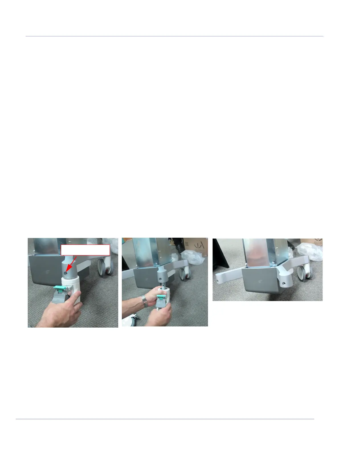
8-6-6-4 Casters Removal Procedure
1) Using a 6mm Allen key, loosen and remove the screw that secures the wheel shaft in the wheel
securing socket.
2) Lift the chassis sufficiently to allow the wheel to drop down out of the wheel securing socket.
3.) Remove the wheel.
8-6-6-5 Casters Installation Procedure
1) Carefully lift the chassis sufficiently to allow insertion of the replacement wheel shaft into the wheel
securing socket.
Note: When installing the swivel lock wheel, lock the swivel before installing it to determine the
installation direction.
2) Push the wheel shaft all the way up into the socket, then gently lower the chassis to the ground.
3.) Apply LOCTITE® 243™ on the Allen screw.
Refer to Table 9-7 on page 9-6.
Figure 8-81 Removing the Caster Wheels
Release the screw
Caster Wheels Disconnected

 Loading...


